
Heat shielding for internal fuel manifolds

Active Publication Date: 2020-06-18
COLLINS ENGINE NOZZLES INC
View PDF0 Cites 10 Cited by
  • Summary
  • Abstract
  • Description
  • Claims
  • Application Information

AI Technical Summary

Benefits of technology

The patent describes a fuel injector system that includes an outer support and an inner support with a feed arm extending between them. The system has multiple outlet openings for feeding injection nozzles. A heat shield is spaced apart from the feed arm with an insulative gap. The system also includes vaulted chambers and weight reduction voids in the inner support and manifold portions of fuel passages. The patent also describes a method of making the system using additive manufacturing. The technical effects of the system include improved fuel injection control and improved heat shielding.

Problems solved by technology

Traditional fuel injector and nozzle designs require complex manifolding that can impede air flow from a compressor to the combustor in a gas turbine engine.

Method used


Image

  • Heat shielding for internal fuel manifolds
  • Heat shielding for internal fuel manifolds
  • Heat shielding for internal fuel manifolds

Examples


Embodiment Construction

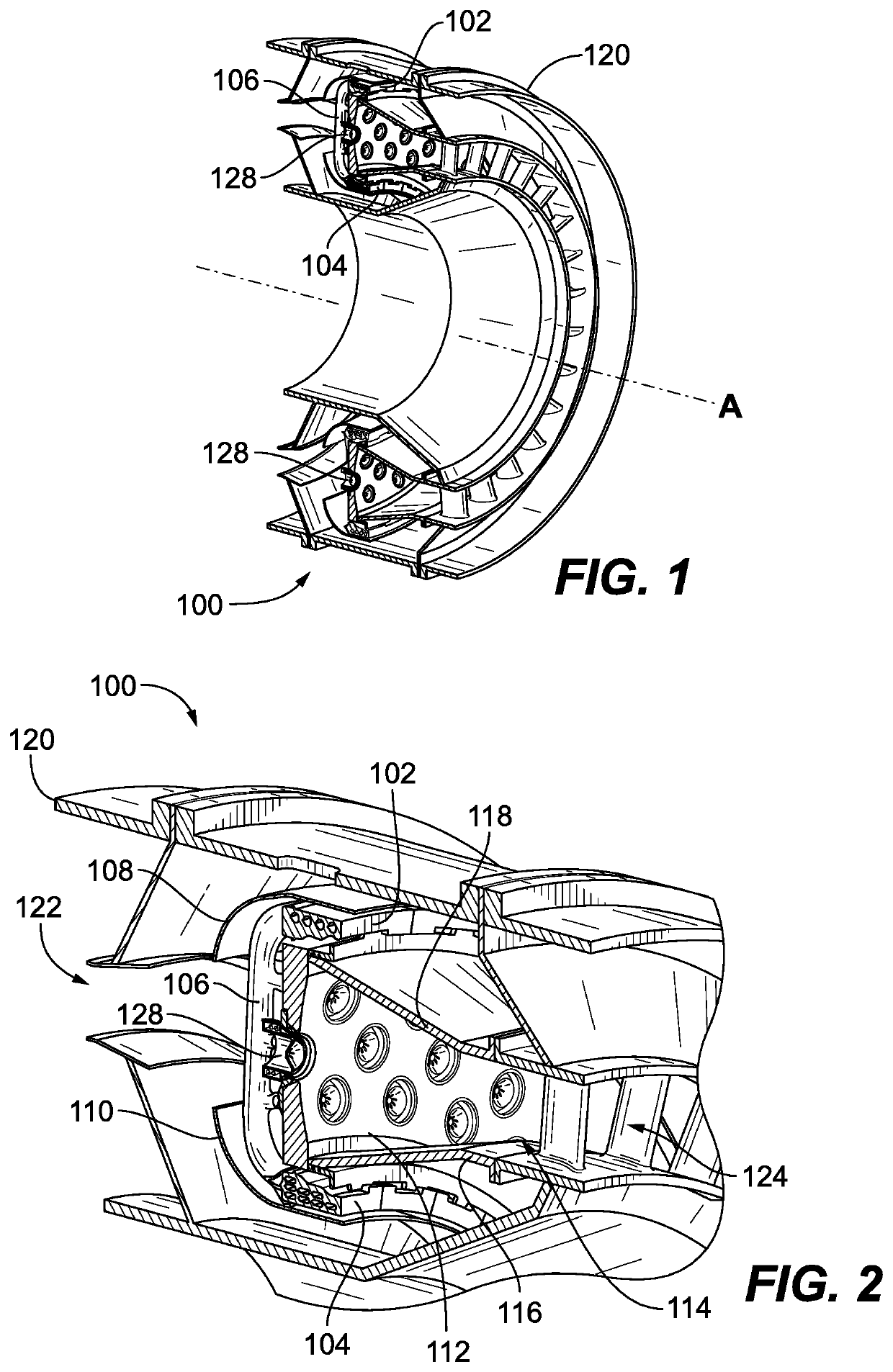
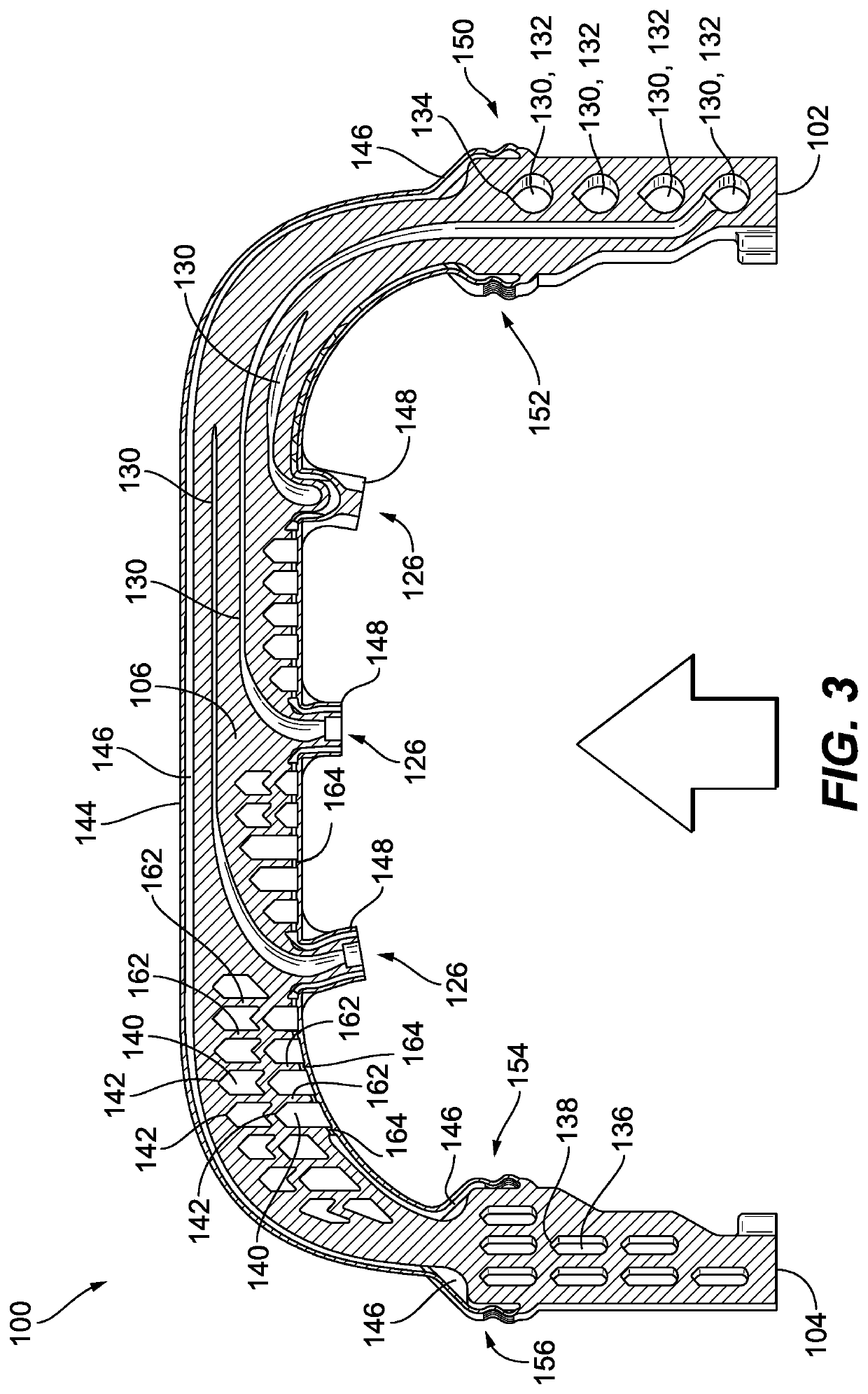
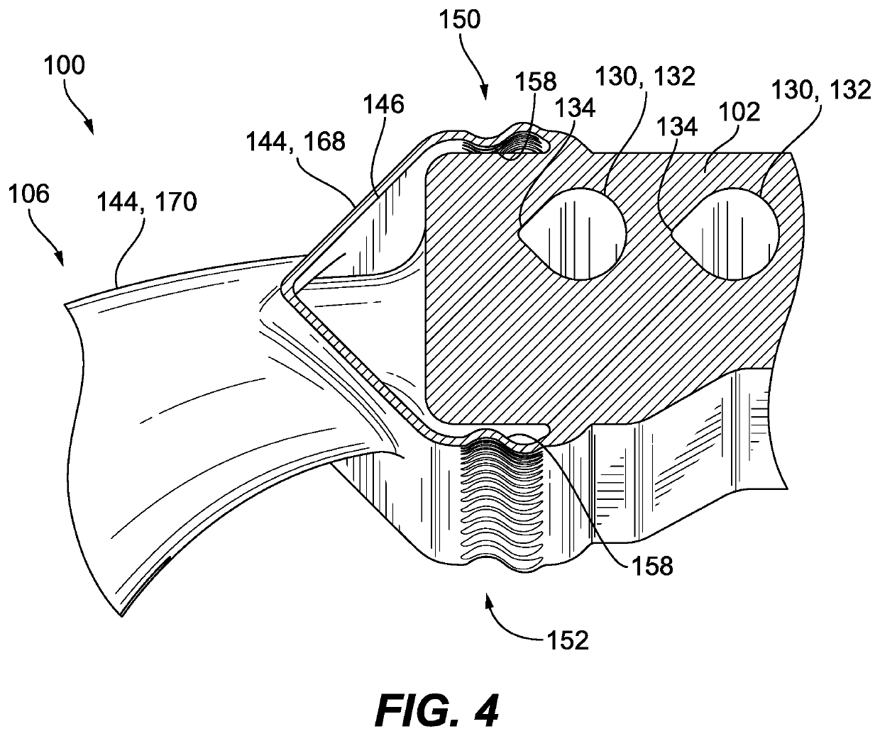
[0019]Reference will now be made to the drawings wherein like reference numerals identify similar structural features or aspects of the subject disclosure. For purposes of explanation and illustration, and not limitation, a partial view of an exemplary embodiment of a fuel injector system in accordance with the disclosure is shown in FIG. 1 and is designated generally by reference character 100. Other embodiments of fuel injector systems in accordance with the disclosure, or aspects thereof, are provided in FIGS. 2-5, as will be described. The systems and methods described herein can be used to provide heat shielding, e.g. in internally manifolded multipoint fuel injection systems such as in gas turbine engines.

[0020]The multipoint fuel injection system 100 includes a circumferentially extending outer support 102 and a circumferentially extending inner support 104, with a plurality of circumferentially spaced apart feed arms 106 extending radially between the inner support 104 and t...


PUM


Abstract

A fuel injector system includes an outer support and an inner support, with a feed arm extending radially between the inner support and the outer support. A plurality of outlet openings extend in an axial direction from the feed arm for feeding respective injection nozzles. The outer support and feed arm define a plurality of fuel passages therethrough to convey fluid from an external source through the outer support and feed arm to the outlet openings. A heat shield extends around the feed arm from the outer support to the inner support. The heat shield is spaced apart from the feed arm with an insulative gap therebetween.

Description

BACKGROUND OF THE INVENTION1. Field of the Invention[0001]The present disclosure relates to combustion, and more particularly to internally manifolded multipoint injection systems such as used for combustion in gas turbine engines.2. Description of Related Art[0002]Multipoint fuel injection systems would benefit from a simple, low cost fuel injector and manifold construction to permit a large number of injectors to be used. Traditional fuel injector and nozzle designs require complex manifolding that can impede air flow from a compressor to the combustor in a gas turbine engine. Advanced engines require thermal protection to prevent fuel from reaching a temperature where it can break down and grow internal carbon build up.[0003]Such conventional methods and systems have generally been considered satisfactory for their intended purpose. However, there is still a need in the art for improved multipoint combustion systems. The present disclosure provides a solution for this need.SUMMAR...

Claims


Application Information

Patent Timeline
IPC IPC(8): F02C7/24F23R3/28F02C7/22
CPCF05D2260/231F05D2240/35F02C7/222F05D2270/3032F02C7/24F23R3/283Y02P10/25
Inventor RYON, JASON A.PROCIW, LEV ALEXANDERZINK, GREGORY A.
Owner COLLINS ENGINE NOZZLES INC
Learn More