Supercharge Your Innovation With Domain-Expert AI Agents!

Capacitive Pressure Transducer

a capacitive diaphragm gauge and pressure transducer technology, applied in the direction of fluid pressure measurement, measurement devices, instruments, etc., can solve the problems of high cost of machining and assembly, and achieve the effect of increasing the accuracy and stability of pressure transducers, obtaining and maintaining stable capacitor gap g, and easy and inexpensive machining

Inactive Publication Date: 2020-06-18
WU GUANGHUA
View PDF0 Cites 0 Cited by
  • Summary
  • Abstract
  • Description
  • Claims
  • Application Information

AI Technical Summary

Benefits of technology

This patent uses a spacer made of low thermal expansion material to improve the accuracy and stability of pressure transducers. This material helps to easily and inexpensively maintain a stable capacitor gap. To keep the transducer's electrodes and diaphragm aligned, the invention also uses a center pin and hole on the electrode disk to support the disk. These technical improvements enhance the performance of pressure transducers.

Problems solved by technology

If the accuracy and repeatability of the gap g rely on that of many components, or on adjustment of spacers, the cost in machining and assembling will be high.

Method used


Image

  • Capacitive Pressure Transducer
  • Capacitive Pressure Transducer
  • Capacitive Pressure Transducer

Examples


Embodiment Construction

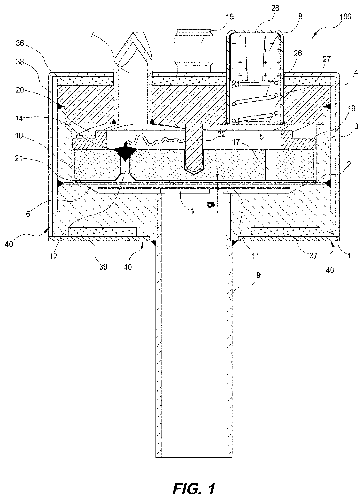
[0012]FIG. 1 is a section view of this invention. The housing of pressure transducer 100 is formed by bottom flange 1, diaphragm 2, middle cylinder 3 and top lid 4, welded together air-tightly. All of these parts are made of stainless steel, preferably 316L VIM / VAR or Inconel.

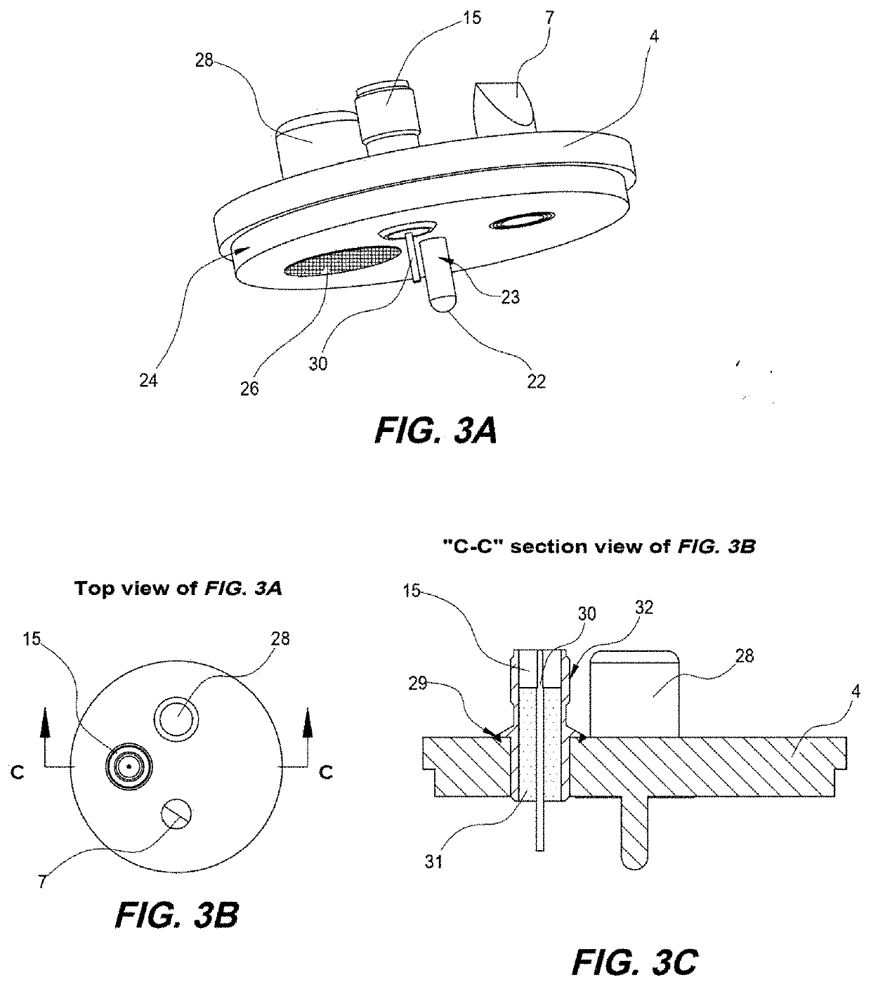
[0013]The housing is divided by diaphragm 2 into two chambers, 5 and 6. By using pinch-off tube 7 to evacuate the chamber 5 first and then sealing the tube 7, activating getter 8 to absorb residual gases, the absolute pressure inside chamber 5 can be kept close to zero. This provides a reference pressure for the pressure transducer 100. Chamber 6 is connected to the pressure to be measured through tube 9, preferably made of stainless steel, welded to the bottom flange 1.

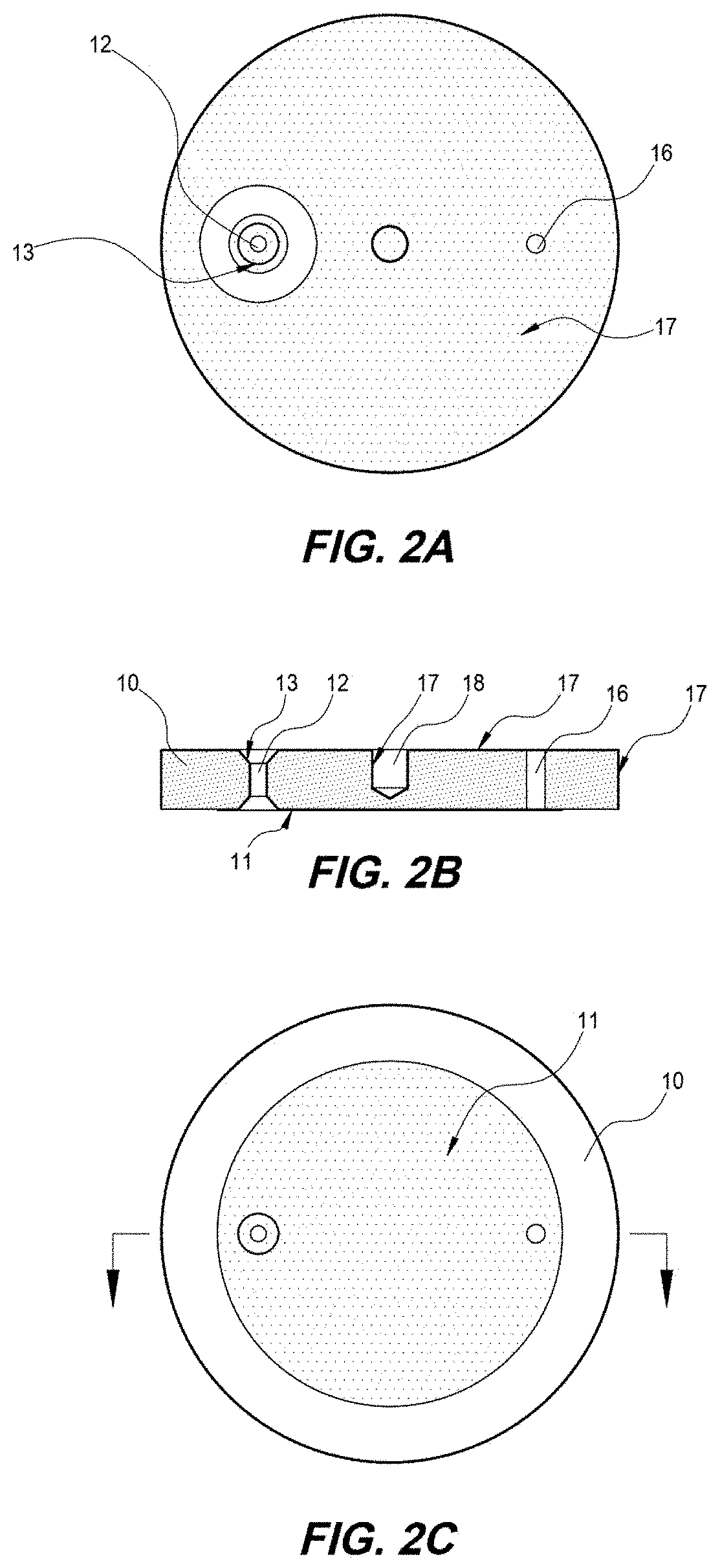
[0014]Disk 10 made of ceramic (AL2O3) has an electrically conductive gold or nickel electrode 11 disposed on its bottom surface (also shown in FIG. 2C). There is a through hole 12 on the disk 10. The internal surface of the hole 12 is plated wit...


PUM

PropertyMeasurementUnit
thermal expansion coefficientaaaaaaaaaa
differential pressureaaaaaaaaaa
friction coefficientsaaaaaaaaaa

Abstract

A variable capacitance type pressure transducer is constructed by electrically conductive diaphragm and electrode disposed on the surface of a dielectric disk. The gap between electrode and diaphragm is formed and solely decided by a spacer made of Super Invar or Invar, which has extra low thermal expansion coefficient. The gap between the electrode and the diaphragm is formed easily and almost no change when temperature of the transducer changes. The dielectric disk is centered with diaphragm radically by a mating between a pin made on the top lid of the pressure transducer and a center hole on the dielectric disk.

Description

FIELD OF THE INVENTION[0001]The present invention is related to capacitive pressure transducers and more specifically to manometers or capacitive diaphragm gauges (CDG).BACKGROUND OF THE INVENTION[0002]Capacitive pressure transducers use one or more variable capacitor(s) to measure pressure. To be accurate and have a high resolution, the gap between two electrodes of the capacitor(s) needs to be small and stable (do not change with temperature and time). As used herein, the gap g is defined as the gap between diaphragm and electrode after assembling of the pressure transducer before it is evacuated for reference pressure, and because the electrode is very thin, the electrode surface and ceramic disk surface are not distinguished. During operation, due to the temperature change and thermal expansion coefficient differences among diaphragm, body and ceramic disk, there will be relative movement among the components, and the gap g changes as a result. To obtain a repeatable initial cap...

Claims


Application Information

Patent Timeline
Patent Type & Authority Applications(United States)
IPC IPC(8): G01L9/00G01L19/00G01L19/14
CPCG01L9/0075G01L19/0061G01L19/14G01L19/04
Inventor WU, GUANGHUA
Owner WU GUANGHUA
Features
  • R&D
  • Intellectual Property
  • Life Sciences
  • Materials
  • Tech Scout
  • Unparalleled Data Quality
  • Higher Quality Content
  • 60% Fewer Hallucinations
Learn More