
Implant with sensor assembly

Active Publication Date: 2020-06-25
BIOTRONIK
View PDF5 Cites 0 Cited by
  • Summary
  • Abstract
  • Description
  • Claims
  • Application Information

AI Technical Summary

Benefits of technology

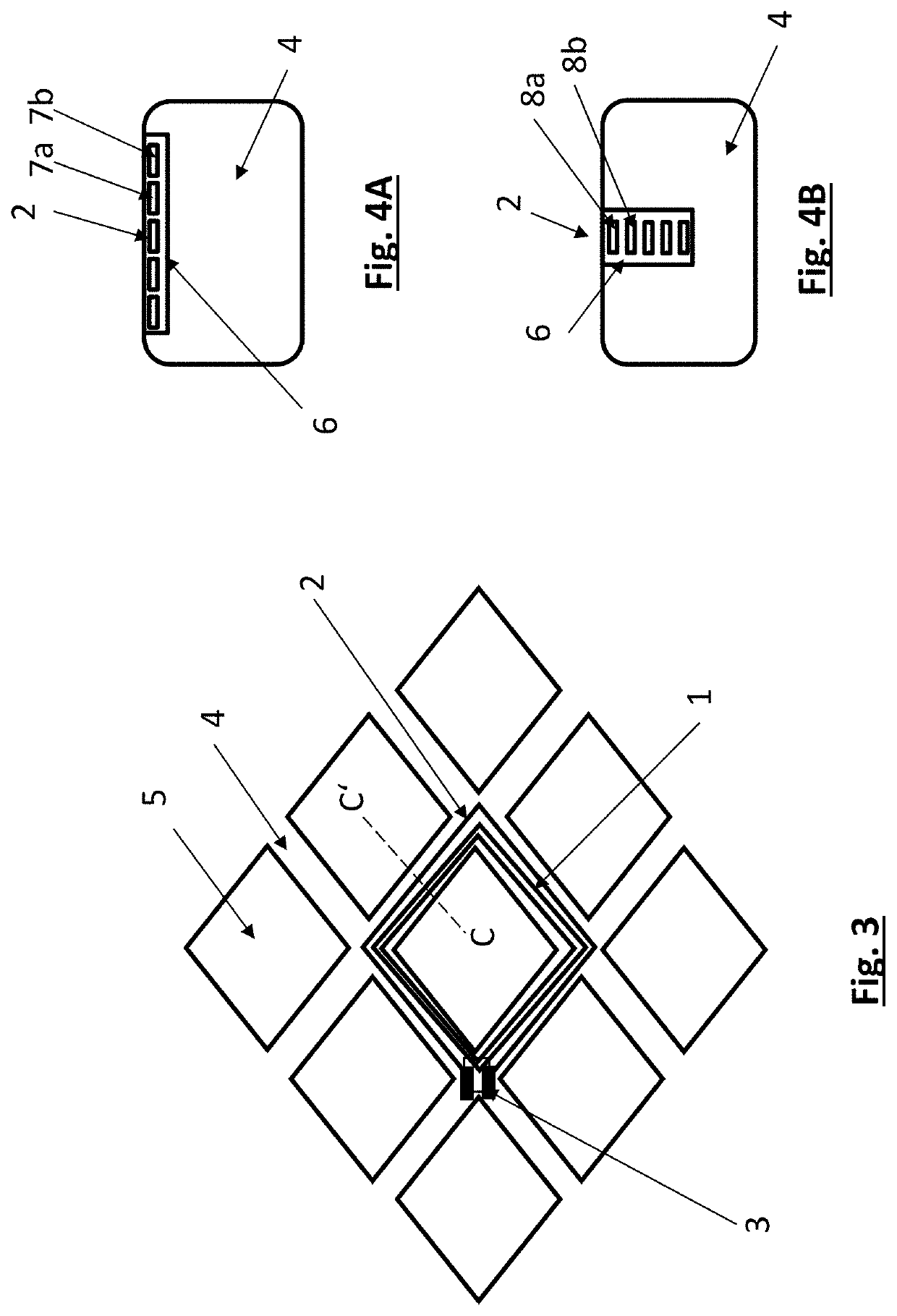
[0030]This embodiment of the invention is particularly preferred and suitable for research. The sensor assembly according to the invention offers a simple possibility for determining the endothelialization of a stent over time. The sensor assembly can be mounted on the main structure (the main frame) of the stent or particularly preferably can be integrated in the main structure of the stent. In this case, indentations are cut into the stent struts by using laser (for example using a material-removing femtosecond laser), into which the electrical conductors are fitted with their insulation and the partially ins

Problems solved by technology

The capacitor is not fully insulated with respect to the surrounding

Method used


Image

  • Implant with sensor assembly
  • Implant with sensor assembly
  • Implant with sensor assembly

Examples


Example

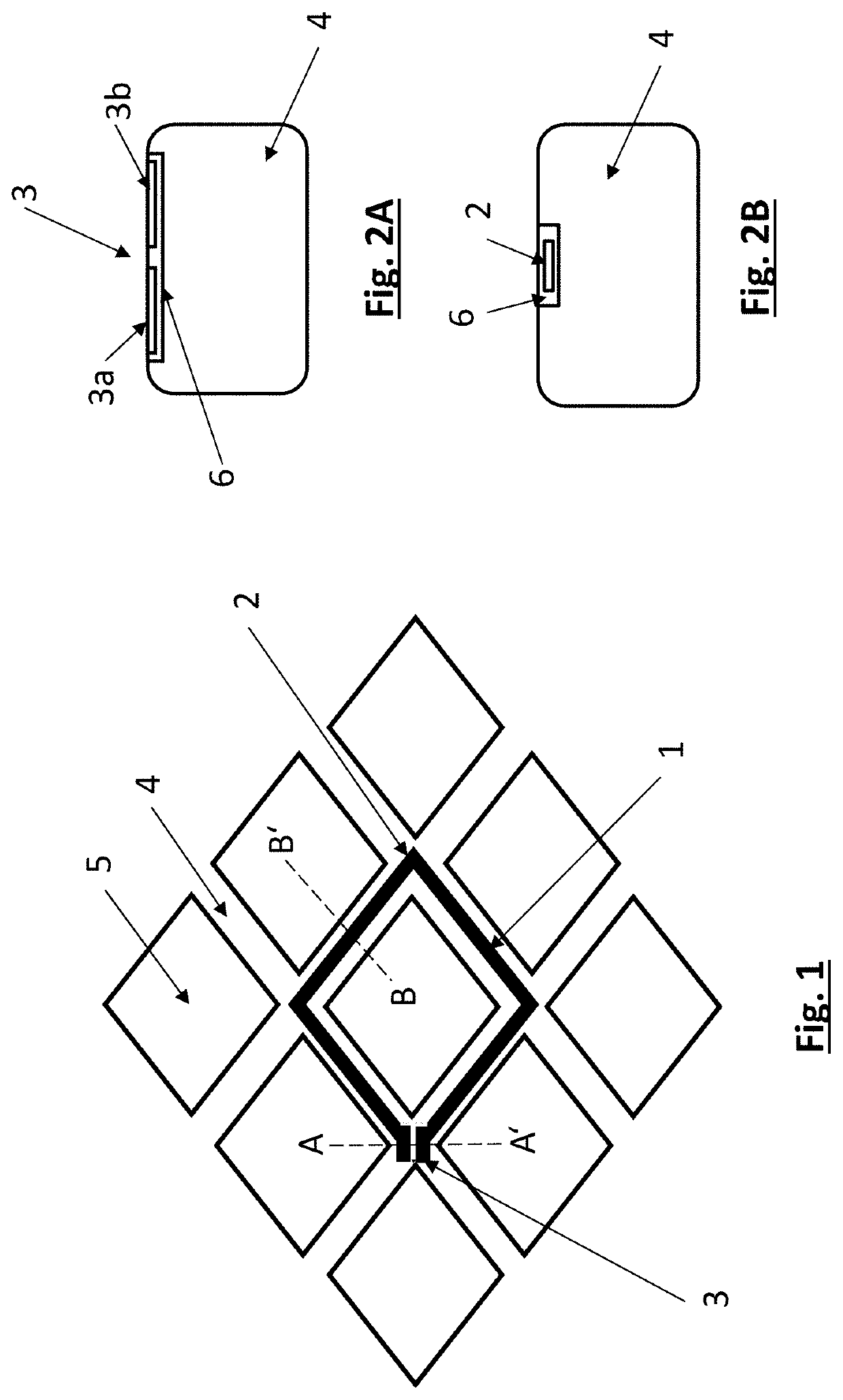
[0045]Referring now to the figures of the drawings in detail and first, particularly, to FIG. 1 thereof, there is seen a detail of a planar development of a stent with stent struts 4 forming a main structure and free spaces 5 formed between the struts. A cell includes the simplest embodiment of a sensor assembly according to the invention, which is formed of a conductor 2 and a capacitor 3.

[0046]Both the conductor 2 and the capacitor 3 are integrated in the main structure of the stent, as is shown by the sections along lines AA′ (FIG. 2A) and BB′ (FIG. 2B). The stent strut 4 is provided with a recess filled by the conductor 2 and associated insulation 6 (FIG. 2B). As shown by the section along line BB′ in FIG. 2A, the capacitor 3 is also integrated in a recess in the stent strut 4. In this case, however, the electrical insulation 6 is disposed only on the sides towards the stent strut 4. Upwardly in FIG. 2A (luminally in the case of implantation), the capacitor 3 is not electrically...


PUM


Abstract

An implant (in particular a stent) includes a main structure and a sensor assembly for measuring a body parameter. The sensor assembly includes at least one electrical conductor and at least one capacitor which are connected in such a way that the conductor and the capacitor form at least one electrical resonant circuit. The electrical conductor is surrounded by an electrical insulation. The electrical conductor is in the form of a coil having at least one turn. The capacitor is in contact at least on one side with the surrounding environment and its capacitance changes depending on the body parameter that is to be determined.

Description

CROSS-REFERENCE TO RELATED APPLICATION[0001]This is a continuation application, under 35 U.S.C. § 120, of copending International Application PCT / EP / 2018 / 075905, filed Sep. 25, 2018, which designated the United States; this application also claims the priority, under 35 U.S.C. § 119, of German Patent Application DE 10 2017 122 820, filed Sep. 29, 2017; the prior applications are herewith incorporated by reference in their entirety.BACKGROUND OF THE INVENTIONField of the Invention[0002]The present invention relates to an implant having a main structure and a sensor assembly for measuring a body parameter, wherein the sensor assembly includes at least one electrical conductor and at least one capacitor which are connected in such a way that the conductor and the capacitor form at least one electrical resonant circuit.[0003]The invention will be described hereinafter on the basis of an intraluminal endoprosthesis, in particular on the basis of a stent, wherein the sensor assembly is in...

Claims


Application Information

Patent Timeline
IPC IPC(8): A61B5/00A61F2/06A61B5/02A61B5/145
CPCA61B5/02007A61F2/06A61B5/14503A61B5/6862A61F2/86A61B5/14546
Inventor DEGEN, NICOLASFINNBERG, THOMAS
Owner BIOTRONIK
Learn More