Bladder monitoring

a bladder and monitoring technology, applied in the field of bladder monitoring system, can solve the problems of reducing the battery life of the apparatus, affecting the accuracy of bladder volume estimation provided by the apparatus, and affecting the accuracy of bladder volume estimation in certain scenarios

Inactive Publication Date: 2020-06-25
KONINKLJIJKE PHILIPS NV
View PDF0 Cites 4 Cited by
  • Summary
  • Abstract
  • Description
  • Claims
  • Application Information

AI Technical Summary

Benefits of technology

[0010]In some embodiments of the present invention, the bladder monitoring device does not necessarily form part of the bladder monitoring system, as the data processing of such a bladder monitoring device may be performed on a separate device comprising the signal processor, e.g. a remote (electronic) device forming the bladder monitoring system. In order to maintain battery life, the processing of the echo signals acquired with the phased array may be performed on a remote device containing the signal processor, e.g. a wearable smart device such as a smart watch, a portable smart device such as a mobile phone or tablet computer, a laptop computer, a personal computer or the like, as such signal processing typically is rather computationally intensive. To this end, the wearable bladder monitoring device may be configured to perform some pre-processing of the echo signals, e.g. down conversion or the like, in order to reduce the amount of data that needs to be communicated to the remote device, thereby further extending battery life. However, in an alternative embodiment the wearable bladder monitoring device further comprises the signal processor, thereby providing a self-contained device, which may be configured to communicate minimal amounts of data, e.g. processing results, to a remote device, e.g. for visualization purposes.
[0011]In an embodiment, the wearable bladder monitoring device further comprises an orientation sensor for determining an orientation of the subject, and wherein the signal processor is adapted to determine an orientation of the wearable bladder monitoring device relative to the pelvic bone based on beam angle information associated with the at least one of said echo signals and an orientation signal from the orientation sensor. Such an orientation sensor, e.g. an accelerometer or the like, may be used to help determine the body posture of the subject, to further aid the accuracy of any bladder data processing, e.g. bladder volume estimation.
[0012]For example, the wearable bladder monitoring device may further comprise a data storage device storing a plurality of bladder models, each associated with a particular orientation of the subject, wherein the signal processor is adapted to retrieve the defined bladder model from the data storage device based on the received orientation signal. In this manner, a bladder model that is particularly accurate for a particular body posture of the subject may be deployed, e.g. in response to the information provided with the orientation sensor, to further improve the accuracy of the processing of the bladder monitoring data acquired with the phased array.
[0014]In a particularly advantageous embodiment, the signal processor is further adapted to, for each echo signal in said subset, calculate a first optimal frequency of its associated ultrasound beam for imaging an anterior boundary of the bladder; calculate a second optimal frequency of its associated ultrasound beam for imaging a posterior boundary of the bladder; instruct the phased array controller to generate at least one further ultrasound beam under the beam angle of the associated ultrasound beam with the phased array, said at least at least one further ultrasound beam having a frequency based on at least one of the first optimal frequency and the second optimal frequency; and estimate the diameter of the subject's bladder for said beam angle from the at least one further echo signal of the at least one further ultrasound beam. This facilitates a more accurate determination of the bladder diameter as the opposing boundaries (wall portions) of the bladder are more accurately imaged, thereby improving the accuracy of the interpretation of the bladder data acquired with a phased array, e.g. an estimated bladder volume and / or fill level. The at least one further ultrasound beam may comprise a first further ultrasound beam having the first optimal frequency and a second further ultrasound beam having the second optimal frequency; or a further ultrasound beam having a frequency that is based on the first optimal frequency and the second optimal frequency.
[0016]The securing means may include a strap, e.g. a belt, attached to the wearable bladder monitoring device and / or an adhesive layer on a subject-facing surface of the wearable bladder monitoring device. The adhesive layer is particularly preferred as this is capable of securely fastening the wearable bladder monitoring device with minimal risk of the device accidentally moving into another location relative to the subject's bladder, and has the further advantage of being minimally intrusive compared to the strap, which may be perceived as less comfortable at least by some users.

Problems solved by technology

In practice, this apparatus suffers from a number of drawbacks.
Firstly, it is rather involved in terms of signal processing, which therefore reduces the battery life of the apparatus, even if the bulk of the signal processing is done remotely.
In practice, this fixed relationship does not exist such that the bladder volume estimations provided with this apparatus may be unreliable in certain scenarios, e.g. depending on the body posture of the individual, e.g. the individual standing, lying down, sitting, crouching, and so on.
Such an unimpeded view is typically not available, at least not in adult individuals, as in such individuals the bladder is at least partially obscured by the pelvic bone.

Method used


Image

  • Bladder monitoring
  • Bladder monitoring
  • Bladder monitoring

Examples


Embodiment Construction

[0032]It should be understood that the Figures are merely schematic and are not drawn to scale. It should also be understood that the same reference numerals are used throughout the Figures to indicate the same or similar parts.

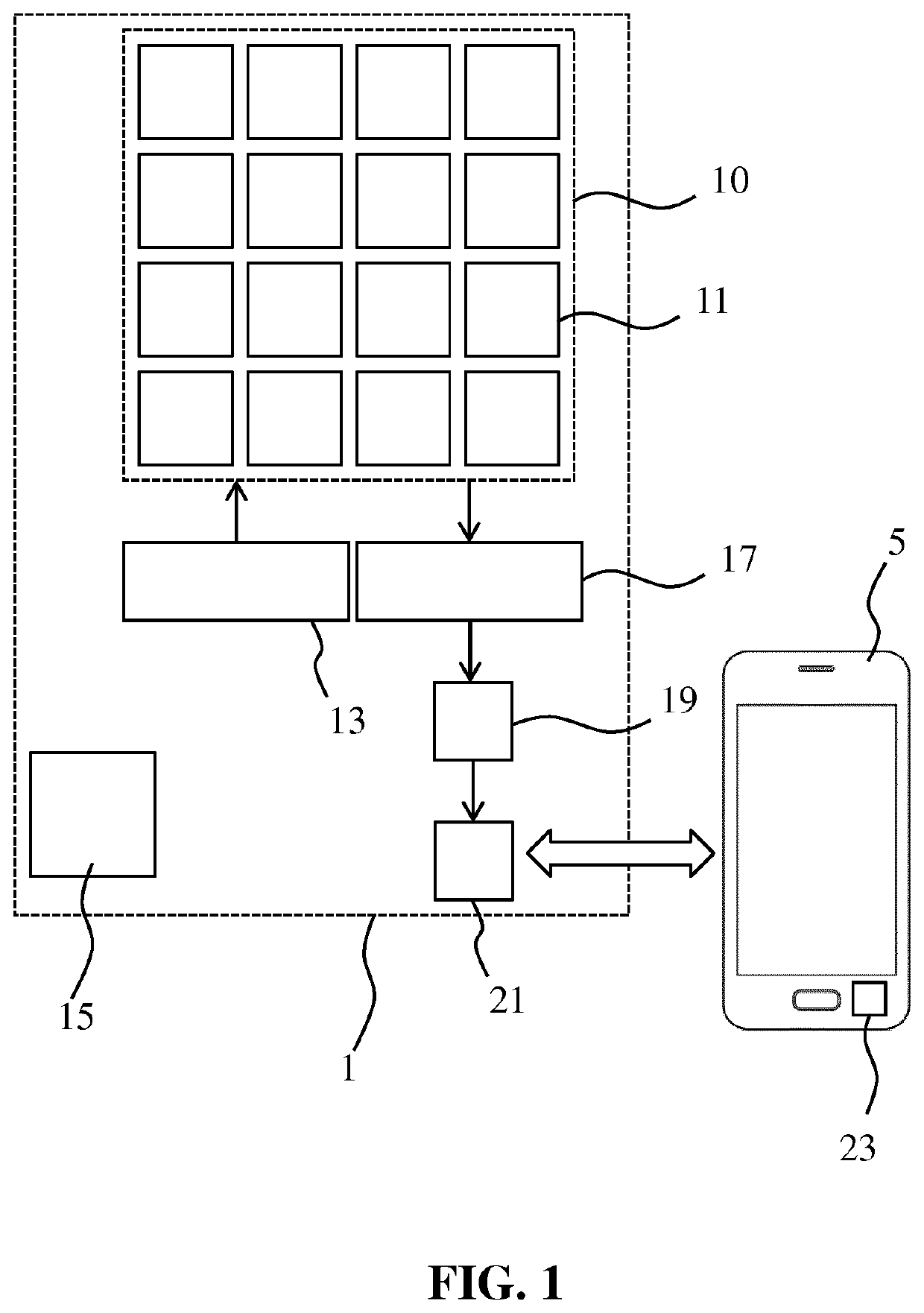
[0033]FIG. 1 schematically depicts a bladder monitoring system according to an example embodiment. The bladder monitoring system comprises a wearable bladder monitoring device 1 that may be secured to an individual (subject) using suitable securing means, such as a strap or belt, or an adhesive layer as will be explained in more detail later. The wearable bladder monitoring device 1 comprises a phased array 10 of ultrasound transducer elements 11 under control of a phased array controller 13. Any suitable type of ultrasound transducer elements 11 may be used for this purpose, e.g. PZT elements, CMUT elements, PMUT elements, and so on, although CMUT elements are particularly preferred, in particular over PZT elements due to their superior (adjustable) resonanc...


PUM


Abstract

The present application discloses a bladder monitoring system comprising a wearable bladder monitoring device (1) including securing means (27, 29) for securing the device to a subject's (40) body; a phased array (11) of ultrasound transducers (10); and a phased array controller (13) adapted to control the phased array to direct a plurality of ultrasound beams (30, 30′, 30″) into the subject's body under a range of beam angles, as well as a signal processor (23) adapted to receive data pertaining to echo signals (31, 31′, 31″) of said ultrasound beams from the phased array. The signal processor is adapted to process said data in order to identify an edge of the subject's pelvic bone (43) proximal to the subject's bladder (41) from data pertaining to at least one of said echo signals; determine an orientation of the wearable bladder monitoring device relative to the pelvic bone based on beam angle information associated with the at least one of said echo signals; and derive bladder information from the data based on the determined orientation. A method of obtaining bladder (volume) information with such a system is also disclosed.

Description

FIELD OF THE INVENTION[0001]The present invention relates to a bladder monitoring system comprising a wearable bladder monitoring device and to a method of monitoring a bladder with such a system.BACKGROUND OF THE INVENTION[0002]In medicine, there is an on-going interest in monitoring the bladder volume of a subject, e.g. a patient. As is well-known per se, the bladder is a triangularly shaped hollow organ for storing urine, with elastic walls such that the bladder can expand upon receiving urine from the kidneys before expelling the urine through the subject's urethra.[0003]There are a number of reasons why such bladder volume monitoring is of interest. For example, the bladder retention volume (i.e. the amount of urine retained by the bladder after the subject's urinating) is an indicator of prostate and urinary tract conditions, which conditions may be triggered by bacteria and other pathogens in the retained urine; consequent bladder stretching is a key contributor to the occurr...

Claims


Application Information

Patent Timeline
Patent Type & Authority Applications(United States)
IPC IPC(8): A61B8/08A61B8/00
CPCA61B8/56A61B8/4488A61B8/0833A61B8/4254A61B8/54A61B8/4227A61B5/1075A61B5/202A61B5/204A61B8/08A61B8/0858A61B8/4245A61B8/4455A61B8/4483A61B8/4494A61B8/4236A61B8/5223G06T7/13
Inventor VAN HEESCH, CHRISTIANUS MARTINUSPAULUSSEN, IGOR WILHELMUS FRANCISCUSDE WILD, NICO MARIS ADRIAANDONATO, KATIABINGLEY, PETERWANG, KEVAN HEESCH, FRANCISCUS HENDRIKUSMERT, AYDINBEZEMER, RICKVAN RENS, ANTONIA CORNELIABUDZELAAR, FRANCISCUS PAULUS MARIA
Owner KONINKLJIJKE PHILIPS NV
Why Eureka
Try Eureka