System and method for engine speed measurement

a technology of engine speed and measurement system, applied in the direction of machines/engines, liquid fuel engines, instruments, etc., can solve the problems of increasing the complexity of the overall system, increasing the overall system complexity, and increasing the implementation cos

Active Publication Date: 2020-06-25
PRATT & WHITNEY CANADA CORP
View PDF2 Cites 2 Cited by
  • Summary
  • Abstract
  • Description
  • Claims
  • Application Information

AI Technical Summary

Problems solved by technology

However, existing speed measurement systems may inaccurately determine engine speed under certain circumstances.
In additio

Method used


Image

  • System and method for engine speed measurement
  • System and method for engine speed measurement
  • System and method for engine speed measurement

Examples


Embodiment Construction

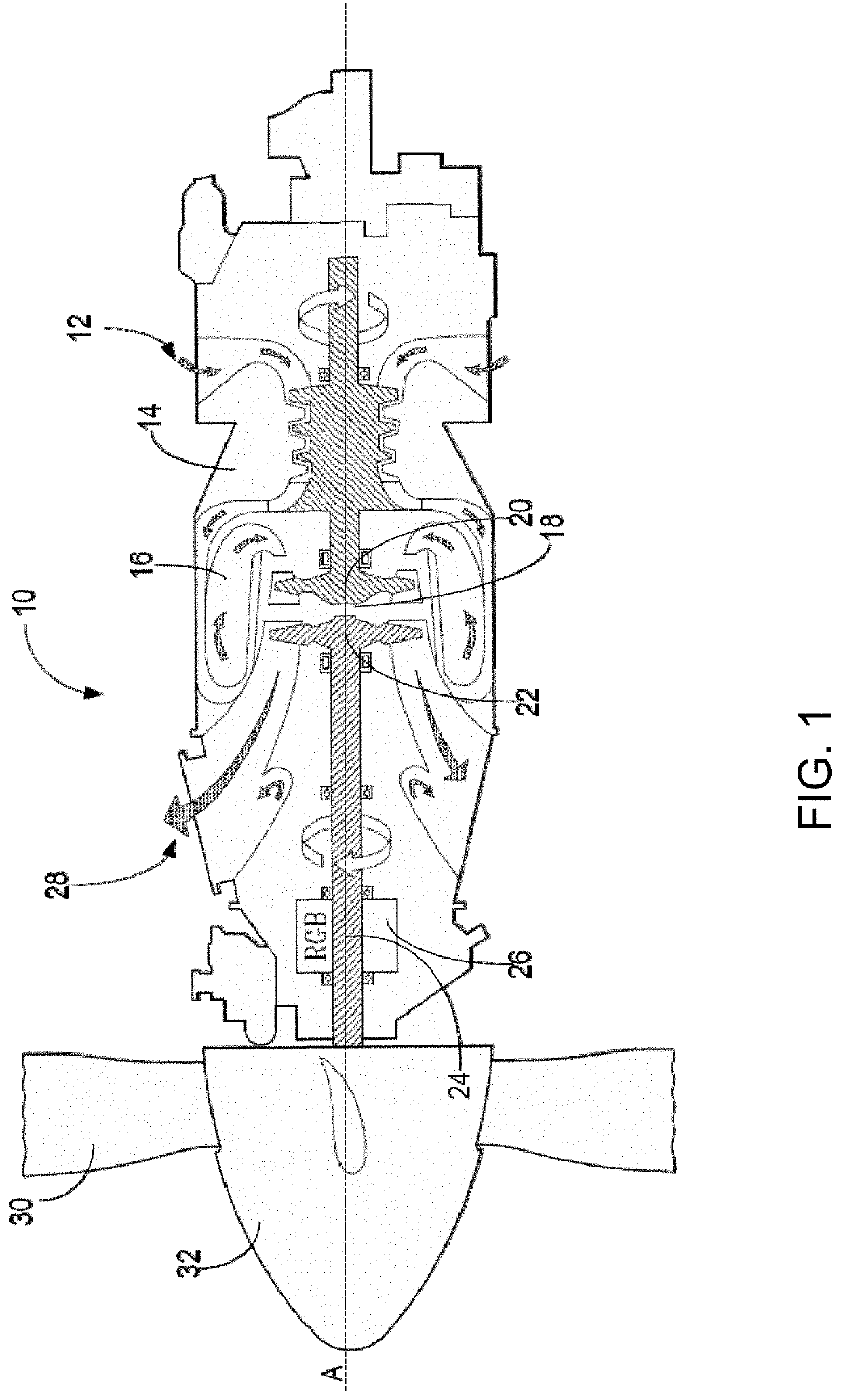
[0017]FIG. 1 depicts a gas turbine engine 10 of a type typically provided for use in subsonic flight. The engine 10 comprises an inlet 12 through which ambient air is propelled, a compressor section 14 for pressurizing the air, a combustor 16 in which the compressed air is mixed with fuel and ignited for generating an annular stream of hot combustion gases, and a turbine section 18 for extracting energy from the combustion gases.

[0018]The turbine section 18 comprises a compressor turbine 20, which drives the compressor assembly and accessories, and at least one power or free turbine 22, which is independent from the compressor turbine 20 and rotatingly drives a rotor shaft (also referred to herein as a propeller shaft or an output shaft) 24 about a propeller shaft axis ‘A’ through a reduction gearbox (RGB) 26. Hot gases may then be evacuated through exhaust stubs 28. The gas generator of the engine 10 comprises the compressor section 14, the combustor 16, and the turbine section 18....


PUM


Abstract

A system and method for measuring a speed of an engine are provided. The engine has a positive displacement pump drivingly connected to a rotor shaft thereof, the pump having an inlet for receiving a fluid supply and an outlet for outputting pressurized fluid. A sensor signal is received from a pressure sensing device provided at an inlet of the pump, the sensor signal comprising a series of periodic oscillations. A frequency of the oscillations is determined, the frequency proportional to a rotational speed of the rotor shaft. The speed of the engine is then determined from the frequency of the oscillations and the speed of the engine as determined is output for controlling operation of the engine.

Description

CROSS REFERENCE TO RELATED APPLICATIONS[0001]This patent application claims priority of U.S. provisional Application Ser. No. 62 / 783,934, filed on Dec. 21, 2018, the entire contents of which are hereby incorporated by reference.TECHNICAL FIELD[0002]The present disclosure relates generally to engine speed measurement.BACKGROUND OF THE ART[0003]Engine speed is typically measured via dedicated speed sensors. However, existing speed measurement systems may inaccurately determine engine speed under certain circumstances. In particular, at low engine speeds, the sensor signal is typically of small magnitude and may therefore be ignored by the engine controller. In addition, provision of additional speed sensors for redundancy can increase the overall system complexity and implementation cost.[0004]Therefore, improvements are needed.SUMMARY[0005]In accordance with a broad aspect, there is provided a system for measuring a speed of an engine, the system comprising a positive displacement pu...

Claims


Application Information

Patent Timeline
IPC IPC(8): G01P3/44F04C29/00F04C29/12
CPCF04C29/0078F04C29/124F05B2270/327F05B2210/302G01P3/443F04C2240/54G01P3/28F04C2/18F04C2270/14F04C14/28G01P1/00G01P3/22G01P3/44G01M15/09
Inventor SHENOUDA, ANTWAN
Owner PRATT & WHITNEY CANADA CORP
Why Eureka
Try Eureka