Semiconductor device, radio terminal device, radio communication system and communication method of radio terminal device

a technology of radio terminal device and electromagnetic field, which is applied in the direction of transmission monitoring, synchronisation arrangement, instruments, etc., can solve the problems of high traffic accident risk, inability to secure a sufficient radio band, and inability to properly perform road-to-vehicle communication and vehicle-to-vehicle communication, so as to reduce the situation and hinder the communication of a vehicle with a high priority for information transmission

Active Publication Date: 2020-06-25
RENESAS ELECTRONICS CORP
View PDF0 Cites 1 Cited by
  • Summary
  • Abstract
  • Description
  • Claims
  • Application Information

AI Technical Summary

Benefits of technology

The semiconductor device described in this patent makes it possible to prevent traffic jams and other obstacles from interfering with high-priority information transmission.

Problems solved by technology

The access control device is installed at a location where there is a high-risk of traffic accidents, such as at an intersection.
Many vehicles gather in places with high-risk of traffic accidents such as intersections.
When many vehicles simultaneously perform data transmission, a sufficient band for radio communication cannot be secured, and the road-to-vehicle communication and the vehicle-to-vehicle communication cannot be properly performed.
However, in Japanese unexamined Patent Application publication No. 2010-124330, since such a viewpoint is not considered, there is a possibility that the radio communication cannot be properly performed because all bands in the frame are filled.

Method used


Image

  • Semiconductor device, radio terminal device, radio communication system and communication method of radio terminal device
  • Semiconductor device, radio terminal device, radio communication system and communication method of radio terminal device
  • Semiconductor device, radio terminal device, radio communication system and communication method of radio terminal device

Examples


first embodiment

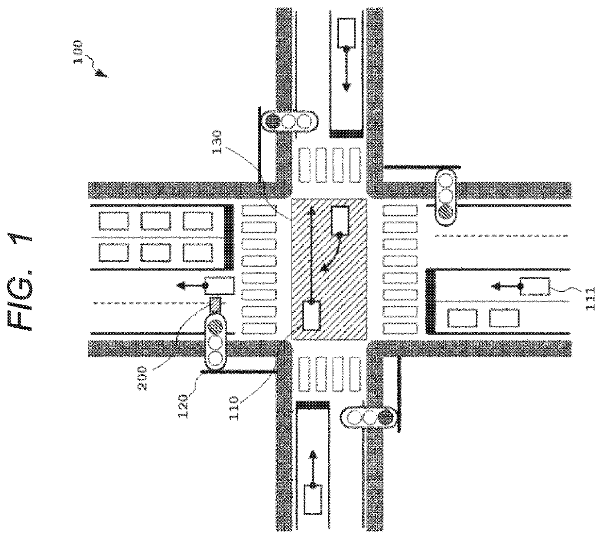
[0035]FIG. 1 is a diagram illustrating an example of a configuration of a communication system 100 according to a first embodiment. As shown in FIG. 1, the communication system 100 includes a vehicle 110, a vehicle 111, vehicles which will be described later, and a radio control device 200. Each vehicle mounts a radio terminal device 300 (not shown) which will be described later. Moreover, FIG. 1 shows an intersection where a road heading in an upper and lower direction of the drawing and a road heading in a right and left direction of the drawing intersect. An intersecting part 130 is a part where these two roads cross each other. Each arrow extending from the vehicle indicates a travelling direction of the vehicle. In FIG. 1, since a signal of the road heading in the upper and lower direction is a red signal, the vehicles traveling on the road heading in the upper and lower direction are stopped or slowing down for stopping. On the other hand, since a signal of the road heading in...

second embodiment

[0128]Next, a second embodiment will be described. In the second embodiment, a processing unit 350a which is another embodiment of the processing unit 350 according to the first embodiment will be described. FIG. 12 is a block diagram showing an example of a configuration of the processing unit (PU) 350a included in a radio terminal device 300a according to the second embodiment. In the second embodiment, configurations of the radio terminal device 300a other than the processing unit 350a may be the same as those shown in FIG. 4. Therefore, their descriptions are omitted here. Further, components of the processing unit 350a described in FIG. 12 having the same functions as those of the processing unit 350 described in FIG. 5 are denoted by the same reference numerals, and the descriptions thereof are omitted.

[0129]As shown in FIG. 12, the processing unit 350a includes a control information monitoring unit (CIMU) 400 in addition to the configuration shown in FIG. 5. The control infor...

third embodiment

Modification of Third Embodiment

[0152]Next, a modification of the third embodiment will be described. In the above described third embodiment, a channel use rate is calculated by the radio terminal device 300b, but calculation processing of the channel use rate can also be performed by the radio control device 200. FIG. 17 is a block diagram showing an example of a configuration of a processing unit (PU) 250b included in a radio control device 200b according to the modification of the third embodiment. In the modification of the third embodiment, configurations of the radio control device 200b other than the processing unit 250b may be the same as those shown in FIG. 2. Therefore, their descriptions are omitted here. Further, components of the processing unit 250b described in FIG. 17 having the same functions as those of the processing unit 250 described in FIG. 3 are denoted by the same reference numerals, and the description thereof are omitted.

[0153]As shown in FIG. 17, the proc...


PUM


Abstract

A semiconductor device includes a communication unit which receives a frame at a first transmission period, demodulates control information from a received frame, modulates transmission data, and broadcasts a modulated transmission data at a second transmission period as a radio frequency packet signal, a period determination unit which determines the second transmission period based on vehicle information, and a transmission and reception control unit which generates a transmission timing trigger signal for determining a transmission timing of the transmission data based on the control information and the second transmission period, and outputs the transmission data to the communication unit in synchronization with the transmission timing trigger signal. The second transmission period is equal to or longer than the first transmission period.

Description

CROSS-REFERENCE TO RELATED APPLICATIONS[0001]The disclosure of Japanese Patent Application No. 2018-238713 filed on Dec. 20, 2018 including the specification, drawings and abstract is incorporated herein by reference in its entirety.BACKGROUND[0002]The present disclosure relates to a semiconductor device, a radio terminal device, a radio communication system and a communication method of the radio terminal device.THE BACKGROUND OF THE INVENTION[0003]Road-to-vehicle communication and vehicle-to-vehicle communication are radio communication systems that support safe driving, which is being researched and developed for the purpose of traffic safety, accident prevention, and traffic congestion alleviation. In the road-to-vehicle communication, vehicles and infrastructure equipment (road-to-vehicle equipment, etc.) perform radio communication, and the vehicles obtain signal information and regulatory information from the infrastructure to support safe driving by drivers. In the vehicle-t...

Claims


Application Information

Patent Timeline
IPC IPC(8): H04W4/40H04W72/00H04W64/00H04W56/00H04B17/327
CPCH04W56/0045H04W64/006H04B17/327H04W72/005H04W4/40G08G1/0104G08G1/087G08G1/052G08G1/048G08G1/091H04B1/3822H04W76/14H04B17/318H04W4/027H04W72/30
Inventor CHANO, HIROSHIFUJITA, SUGURU
Owner RENESAS ELECTRONICS CORP
Why Eureka
Try Eureka