
A lighting driver, lighting circuit and drive method

Active Publication Date: 2020-06-25
SIGNIFY HLDG BV
View PDF0 Cites 0 Cited by
  • Summary
  • Abstract
  • Description
  • Claims
  • Application Information

AI Technical Summary

Benefits of technology

The patent text describes a method for determining the operating current of an LED lighting load and using this information to operate a dimmer function. The method allows for dimming over a wide range (2% to 100%) while maintaining low power loss and low thermal stress on the LED load.

Problems solved by technology

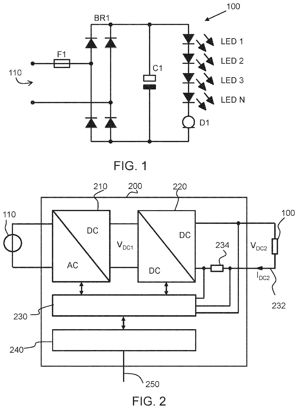
A drawback of such an LED lamp is that it cannot easily be dimmed, for example it cannot be dimmed using a phase-cut dimmer due to high inrush currents in the energy storage buffer capacitor C1.
The lamps of this type are thus generally only suited for non-dimmable applications.
However, in such a case, the range of the DC supply voltage that is supplied to the LED lamp must accurately match the LED string forward voltage in order to enable smooth dimming and to not exceed the power dissipation inside an LED lamp and hence affect its reliability.
Filament LED lamps and related regulated DC power sources are, however, not standardized products so that it is not possible to provide a single DC power source design which is suitable for a large range of LED lamp types.
For example, a regulated DC power source does not know the electric characteristics of the filament lamp such as the number of lamps and the rated power level of an installation.
This will increase power losses and the temperature at the internal linear current regulating device.
As a further consequence, the lighting installation is not optimized due to excessive power losses at the linear current regulating device inside the lamp.

Method used


Image

  • A lighting driver, lighting circuit and drive method
  • A lighting driver, lighting circuit and drive method

Examples


Embodiment Construction

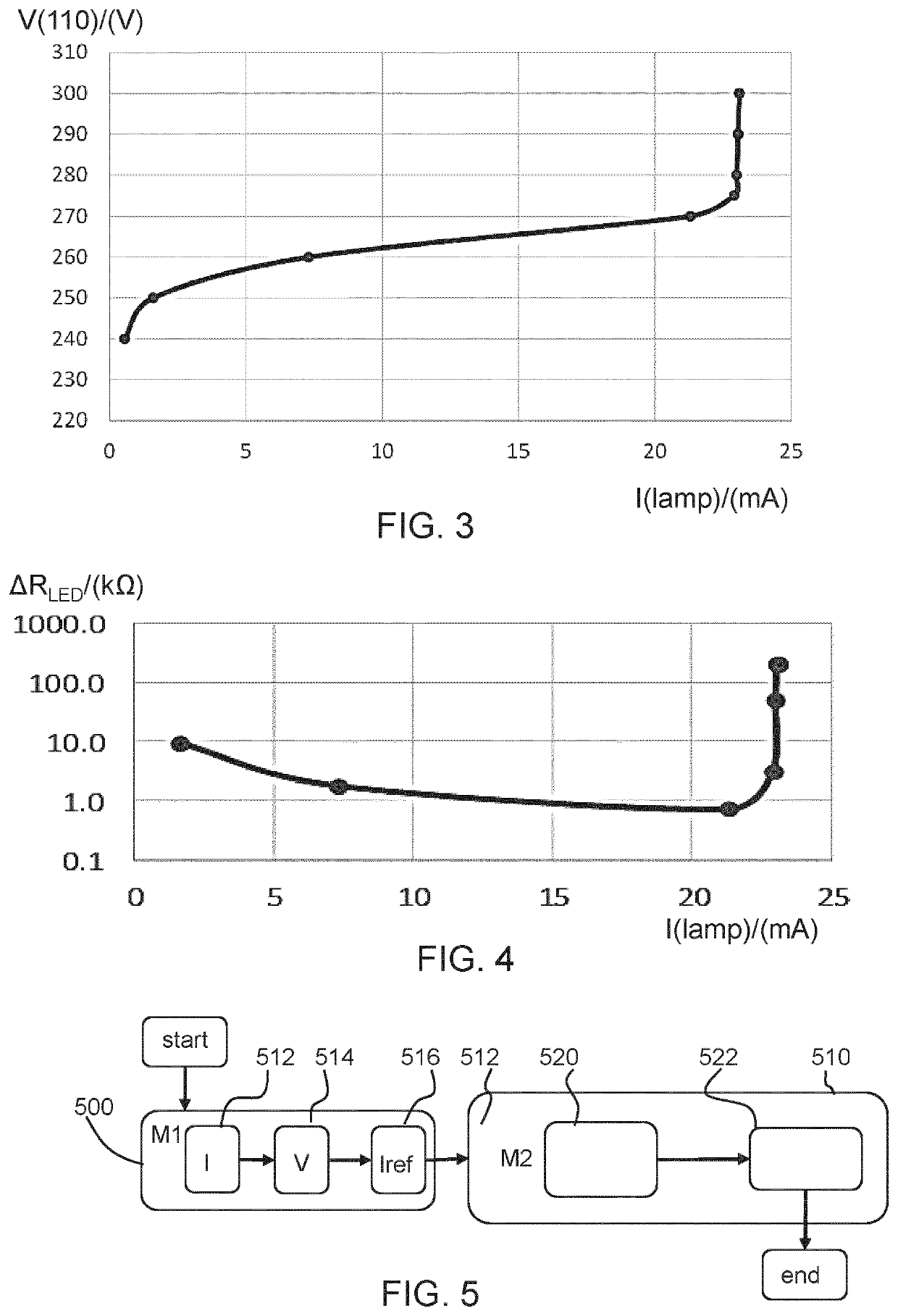
[0068]The invention provides a lighting driver for driving an unknown lighting load based on a controlled DC driver, with a controlled output current. It is used in a first, test mode of operation to detect at least one operating current of the lighting load and in a second, operating, mode of operation to deliver a current to the lighting load in dependence on the detected operating current and preferably also in dependence on a dimming setting. In this way, the driver configures its output to the load based on an analysis of the current characteristics of the load, such as the maximum rated current.

[0069]FIG. 2 shows an example of a lighting driver 200 in accordance with an example of the invention. The lighting driver functions as a regulated DC power source, in particular having a regulated output current, and it is able to implement a dimming function for lighting systems which make use of (usually non-dimmable) retrofit AC LED lamps, such as shown in FIG. 1.

[0070]The example s...


PUM


Abstract

A lighting driver is designed for driving an unknown lighting load and is based on a controlled DC driver, with a controlled output current. It is used in a first mode of operation to determine an operating current of the lighting load and in a second mode of operation to deliver a current to the lighting load in dependence the determined operating current, and optionally also in dependence on a dimming setting. In this way, the driver configures its output to the load based on an analysis of the current characteristics of the load, such as the maximum rated current.

Description

FIELD OF THE INVENTION[0001]This invention relates to a lighting driver, and in particular which makes use of a controlled DC power source for providing dimming capability to LED lamps that are not dimmable by phase-cut dimmers.BACKGROUND OF THE INVENTION[0002]LEDs are driven by DC currents. Thus, an LED driver either has a DC power source or provides AC / DC conversion. In particular, driving an LED luminaire from a mains AC input requires conversion of the AC mains to a DC drive level suitable for driving the LED arrangement.[0003]Different driver designs strive a different balance between cost and performance. A high cost driver typically makes use of a switched mode power supply, which provides AC / DC conversion as well as having feedback control of the output current and / or voltage of the driver.[0004]US2012 / 0187863 and WO2013 / 072784 show example of LED drivers providing a DC current to LEDs. The drivers of these documents can be used with different LED loads and they both monitor...

Claims


Application Information

Patent Timeline
IPC IPC(8): H05B45/14H05B45/44H05B45/54H05B44/00
CPCH05B45/44H05B45/54H05B45/14
Inventor BOEKE, ULRICHBOONEN, PAUL THEODORUS JACOBUS
Owner SIGNIFY HLDG BV
Learn More