
Detection method, device and cartridge for enhancing detection signal intensity

a detection signal and intensity technology, applied in the field of detection methods, can solve the problems of sample not being returned, affecting detection precision, and long response time, so as to improve detection sensitivity, shorten response time, and enhance detection signal intensity

Inactive Publication Date: 2020-07-02
DELTA ELECTRONICS INC
View PDF0 Cites 0 Cited by
  • Summary
  • Abstract
  • Description
  • Claims
  • Application Information

AI Technical Summary

Benefits of technology

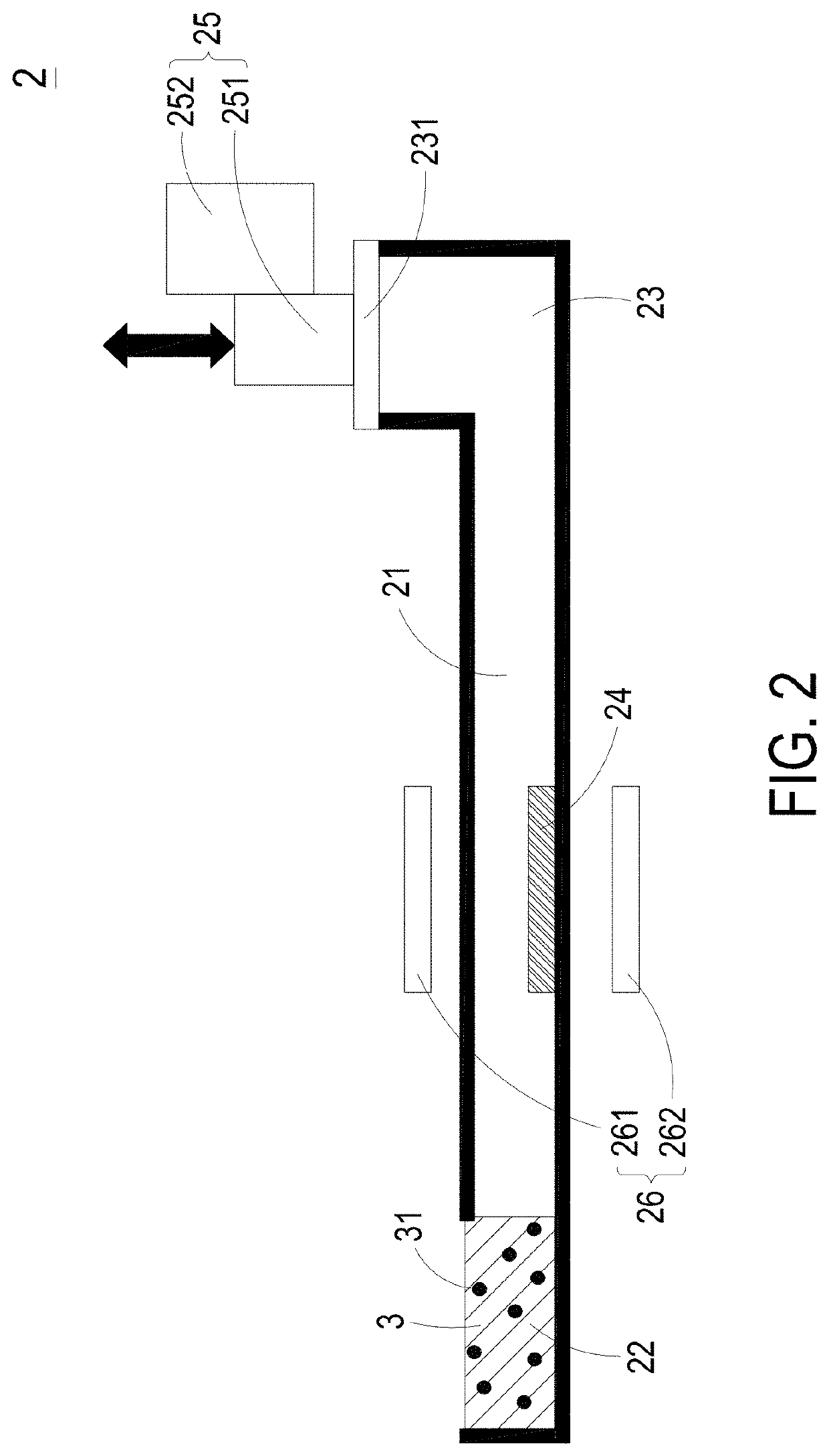
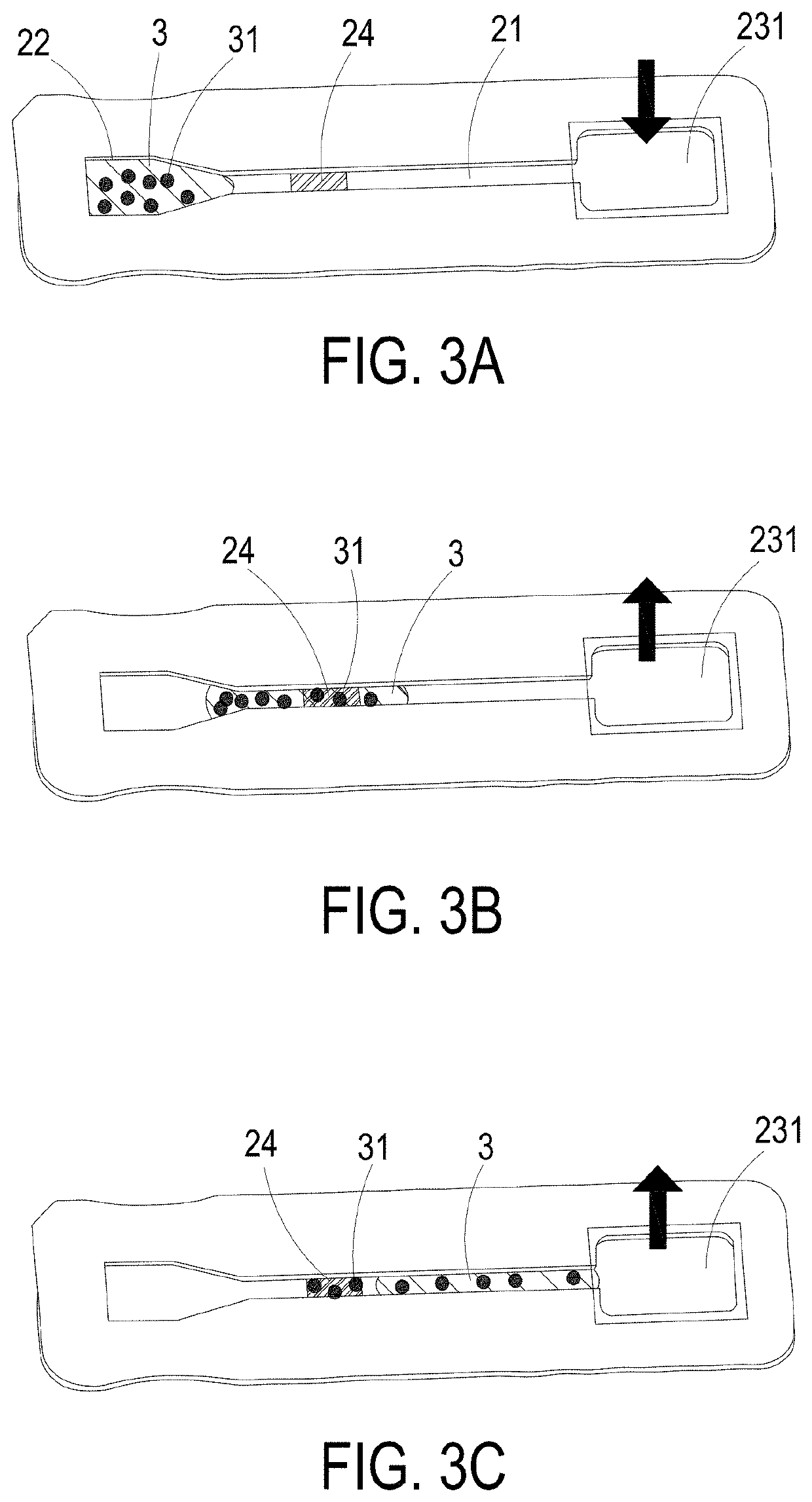
The present invention provides a method, device, and cartridge for improving the detection of signals. This is done by repeating the steps of adding a detection material to a sample, transferring the sample through a reaction area, and adding more detection material to the sample. This process increases the likelihood of combining the detection material with the sample in the reaction area, resulting in better detection sensitivity and faster response time.

Problems solved by technology

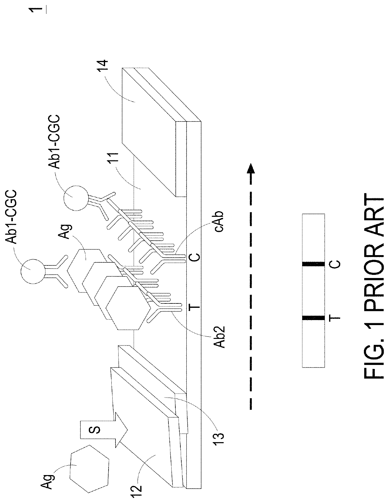
Although these biological detection cartridges can meet the real-time testing requirement and the point-of-care testing requirement, there are still some drawbacks.
For example, since the amount of the loaded sample is not precisely controlled, the detection precision is adversely affected.
Moreover, if no signals are captured by the test line, the sample cannot be returned back because the lateral flow of the sample is in the one-way direction.
In addition, if the concentration of the analyst in the sample is very low, it is necessary to take a long response time to accumulate the identifiable signal on the test line.

Method used


Image

  • Detection method, device and cartridge for enhancing detection signal intensity
  • Detection method, device and cartridge for enhancing detection signal intensity
  • Detection method, device and cartridge for enhancing detection signal intensity

Examples


Embodiment Construction

[0029]The present invention will now be described more specifically with reference to the following embodiments. It is to be noted that the following descriptions of preferred embodiments of this invention are presented herein for purpose of illustration and description only. It is not intended to be exhaustive or to be limited to the precise form disclosed. The drawings of all the embodiments of the present invention are merely schematic and do not represent true dimensions and proportions. Besides, the orientations “upper” and “lower” as used in the following embodiments are merely used to indicate relative positional relationships, and are not intended to limit the present invention.

[0030]The present invention provides a detection method, a detection device and a detection cartridge for enhancing detection signal intensity. Since the signals of the particles or molecules in biological detection are enhanced, the detection result can be obtained more accurately and quickly. When t...


PUM

PropertyMeasurementUnit
pHaaaaaaaaaa
pHaaaaaaaaaa
areaaaaaaaaaaa

Abstract

A detection method for enhancing detection signal intensity is provided. The detection method includes the following steps. Firstly, a detection device is provided. The detection device includes a channel, an inlet port and an air chamber. The air chamber includes an elastic layer. A bonding material is immobilized in the channel and served as a reaction area. Then, a sample containing a detection material is loaded into the inlet port. As the elastic layer is moved upwardly and downwardly, the sample is moved toward the air chamber and the inlet port in a reciprocating manner. Consequently, the possibility of combining the detection material of the sample with the bonding material in the reaction area is increased. Afterwards, an optical signal from the reaction area is measured.

Description

CROSS-REFERENCE TO RELATED APPLICATION[0001]This application claims the benefit of U.S. Provisional Application No. 62 / 785,043 filed on Dec. 26, 2018, and entitled “METHOD AND DEVICE FOR ENHANCING DETECTION SIGNAL”, the entirety of which is hereby incorporated by reference. This application also claims the priority to China Patent Application No. 201910800830.5 filed on Aug. 28, 2019, and entitled “DETECTION METHOD, DEVICE AND CARTRIDGE FOR ENHANCING DETECTION SIGNAL INTENSITY”, the entirety of which is hereby incorporated by reference.FIELD OF THE INVENTION[0002]The present invention relates to a detection method, a detection device and a detection cartridge for enhancing detection signal intensity, and more particularly to a detection method, a detection device and a detection cartridge for enhancing detection signal intensity for in vitro detection.BACKGROUND OF THE INVENTION[0003]A biological detection device is employed to allow a specific biological material (such as nucleic a...

Claims


Application Information

Patent Timeline
Patent Type & Authority Applications(United States)
IPC IPC(8): B01L3/00G01N21/75
CPCB01L3/502715B01L3/50273G01N21/75B01L2300/06G01N2021/752B01L2400/0475B01L2200/0647B01L2200/16B01L2300/0816B01L2300/123B01L3/502761B01L2300/0627B01L2400/0478B01L2300/069B01L2300/0654B01L2300/0663B01L2400/0481
Inventor CHIOU, CHI-HANLIAO, SHU-HSIENTSAI, YU-HSUANCHANG, CHING-YU
Owner DELTA ELECTRONICS INC
Learn More