Welding device and welding method

Active Publication Date: 2020-07-02
TOYOTA JIDOSHA KK
View PDF0 Cites 3 Cited by
  • Summary
  • Abstract
  • Description
  • Claims
  • Application Information

AI Technical Summary

Benefits of technology

[0012]In the welding method according to the present disclosure, since the inert gas is introduced to the exposed portion from the downstream side in the scanning direction of the laser light, and while suctioning the inert gas introduced to the exposed portion from the upstream side in the scanning direction of the laser light to discharge the inert gas to the outside, the intended weld line of the workpiece is irradiated with the laser light, the fumes and the dust generated during welding can be removed by pushing and flowing them to the outside, thereby ensuring the reduced accumulation of the fumes and the dust. Moreover, since the inert gas is introduced from the opposite direction with respect to the scanning direction of the laser light (that is, direction from downstream side toward upstream side) to push and flow the fumes and the dust, interference by the fumes and the dust to the laser light can be further reduced compared with a case where, for example, the inert gas is introduced along the scanning direction of the laser light (that is, direction from upstream side toward downstream side). As a result, the accumulation of the fumes and the dust can be reduced, thereby ensuring the improved quality of laser welding.
[0013]The welding method according to the present disclosure may further include preparing that includes sandwiching the workpiece by relatively bringing the second jig on which the workpiece is placed close to the first jig before the welding. The preparing may include introducing the inert gas to the exposed portion from the downstream side in the scanning direction of the laser light while relatively bringing the second jig close to the first jig and introducing the inert gas to an inside of a chamber t

Problems solved by technology

However, since the above-described welding device is insufficient in removing the fumes and the dust generated during welding, the fumes and the

Method used


Image

  • Welding device and welding method
  • Welding device and welding method
  • Welding device and welding method

Examples


Example

[0024]While the following describes an embodiment of a welding device and a welding method according to the present disclosure with reference to the drawings, before that, a structure of a workpiece to be welded is briefly described based on FIG. 1 and FIG. 2.

Workpiece

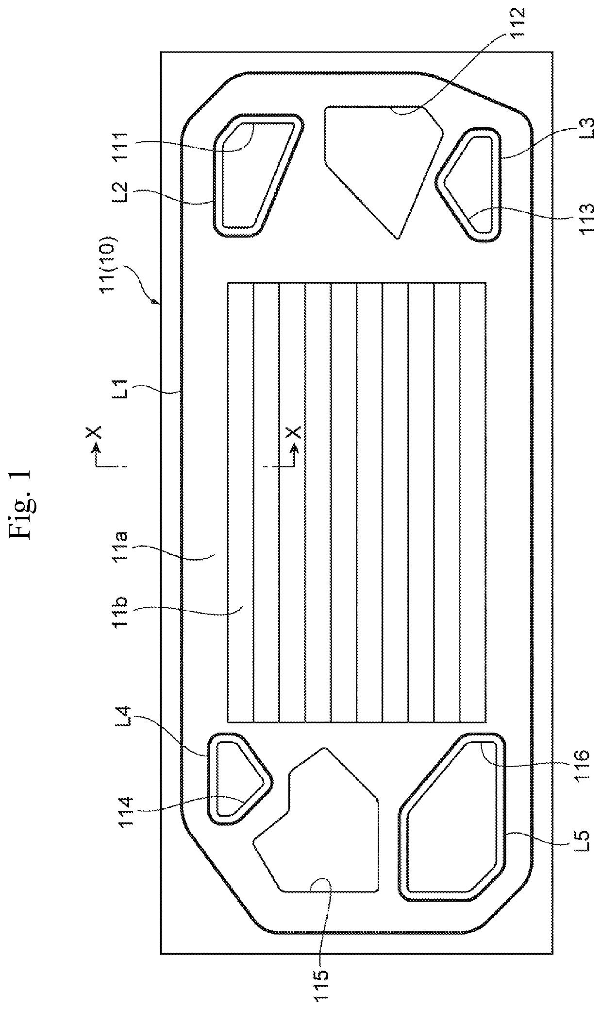
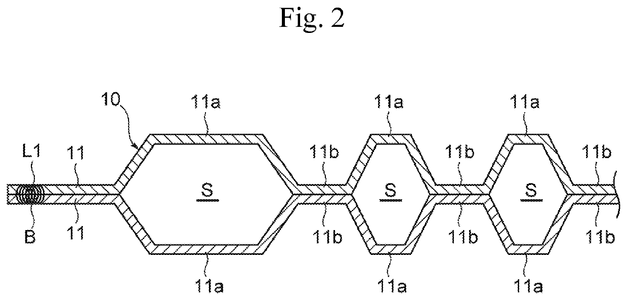
[0025]FIG. 1 is a plan view illustrating a workpiece. FIG. 2 is a cross-sectional view taken along the line X-X in FIG. 1. As illustrated in FIG. 1 and FIG. 2, a workpiece 10 according to this embodiment is two stacked separators 11 used for, for example, a fuel cell. The separator 11 is formed by press forming a metal plate material, such as stainless steel and titanium steel, such that protruding portions 11a and recessed portions 11b are alternately repeated. The two separators 11 are stacked such that the recessed portions 11b of one separator 11 are brought into contact with the recessed portions 11b of the other separator 11. This forms spaces S between the protruding portions 11a of one separator 11 and the prot...


PUM

PropertyMeasurementUnit
Angleaaaaaaaaaa

Abstract

A welding device includes a laser irradiation unit that irradiates a workpiece with a laser light while scanning along an intended weld line of the workpiece, an upper jig arranged on a side of the laser irradiation unit with respect to the workpiece, and a lower jig arranged on an opposite side of the laser irradiation unit side. The upper jig includes an exposed portion that exposes the intended weld line of the workpiece to the laser irradiation unit side, an introduction path that is disposed in a downstream side in a scanning direction of the laser light and introduces an inert gas to the exposed portion, and a discharge path that is disposed in an upstream side in the scanning direction of the laser light and suctions the inert gas introduced to the exposed portion to discharge the inert gas to an outside.

Description

CROSS REFERENCE TO RELATED APPLICATIONS[0001]The present application claims priority from Japanese patent application JP 2018-242912 filed on Dec. 26, 2018, the content of which is hereby incorporated by reference into this application.BACKGROUNDTechnical Field[0002]The present disclosure relates to a welding device and a welding method, in particular, relates to a welding device and a welding method for welding fuel cell separators.Background Art[0003]Conventionally, as a welding device that welds fuel cell separators (hereinafter simply referred to as “separators”), there has been known a welding device described in, for example, WO 2016 / 001992. In the welding device described in WO 2016 / 001992, two sheet-shaped separators in a stacked state are sandwiched between an upper sandwiching member and a lower sandwiching member, and an outer peripheral edge sandwiching member and an inner peripheral edge sandwiching member that constitute the upper sandwiching member have a clearance ir...

Claims


Application Information

Patent Timeline
IPC IPC(8): B23K26/21B23K26/12B23K26/082B23K26/03
CPCB23K26/123B23K26/082B23K26/142B23K26/032H01M8/0202B23K26/21B23K26/702H01M8/0206H01M8/0267B23K2103/14B23K2103/05B23K2101/36B23K2101/18B23K26/244B23K26/26B23K37/0408Y02E60/50H01M8/021
Inventor NAKAMURA, HIDEO
Owner TOYOTA JIDOSHA KK
Why Eureka
Try Eureka