
Connection rod

a technology of connecting rods and rod bodies, applied in the field of connecting rods, can solve the problems of adversely affecting the degree of adjustability of the connection rod, and limited load capacity of the connection rod itself, so as to reduce installation time and cost, improve material properties of solid reacted materials, and shorten the gel time of chemically reacting

Active Publication Date: 2020-07-02
AIRBUS OPERATIONS GMBH
View PDF0 Cites 5 Cited by
  • Summary
  • Abstract
  • Description
  • Claims
  • Application Information

AI Technical Summary

Benefits of technology

The present invention provides a connection rod that allows for easy adjustment during installation and reduces the need for tooling and protective tooling. The design also allows for improved mixing of reactive materials, resulting in better material properties and a faster gel time. The connection rod is versatile and can be used in assemblies with limited tooling space. Overall, the present invention offers improved efficiency and flexibility during installation.

Problems solved by technology

This is especially apparent when assembling non-metallic components, which are being used more often in the aerospace sector, however it is known to also be an issue when assembling metallic components to other metallic components or to non-metallic components.
One disadvantage of the threaded connection rods so far described relates to the maximum load capability of the connection rod 101, which is limited by the strength of engaging the threaded portion of the shaft and the adjustable connectors.
Larger, stronger threads, with a coarser pitch, would increase the strength, however this would the adversely affect the degree of adjustability of the connection rod.
This is not acceptable because the adjustability must be able to cater for the scale of the tolerance variation expected in the assembly, which is normally in increments of 0.01 mm.
The resulting design therefore is a compromise that is always limited in load capability of the connection rod itself or limited in the increments of its adjustability.
A further disadvantage relates to corrosion of the threaded portion of this type of connection rod.
However, corrosion proofing of helical features on a threaded shaft is difficult to achieve due to the complex micro surface geometry to which the corrosion proofing must adhere.
The corrosion proofing is also difficult to keep intact for threaded components that engage one another.
Thus, the corrosion proofing for threaded types of adjustable connection rods is prone to damage and may often become compromised during the connection rods service life, resulting in thread corrosion that requires the corroded connection rod 101 to be taken out of service and repaired.
This increases the cost of maintaining and operating the affected aircraft.
Further disadvantages relate to the costs of installing the threaded type of connection rods, in particular the costs associated with the tooling needed, the length of the installation procedure, and the costs of avoiding with or remediating inadvertent damage caused to surrounding system or structural components during installation.
These costs account for a significant portion of the overall cost associated with using the threaded type of connection rod.
This is normally achieved using torque wrench(es) and takes a significant amount of time and skill in order to achieve the correct installation length of the connection rod that is locked correctly.
This is because the space adjacent to the connection rod in order to attach, rotate and detach one or more torque wrenches is limited.
In some cases, the wrench may slip from engagement with the connection rod, resulting in inadvertent damage to adjacent components, or to the tooling itself.
Protective tooling such as soft padding is sometimes implemented to prevent inadvertent damage, but this increases costs and time taken to install the connection rod.
It also may not avoid damage to the connection rod itself where it engages the torque wrench.
Another undesirable option taken by designers is to position the systems components further away from connections rods to avoid inadvertent damage as is the case in FIG. 1.
A further disadvantage of using threaded type of adjustable connection rods is that sometimes in spite of being desired, they are not a viable design solution because of the tooling space necessary to install them.

Method used


Image

  • Connection rod
  • Connection rod
  • Connection rod

Examples


Embodiment Construction

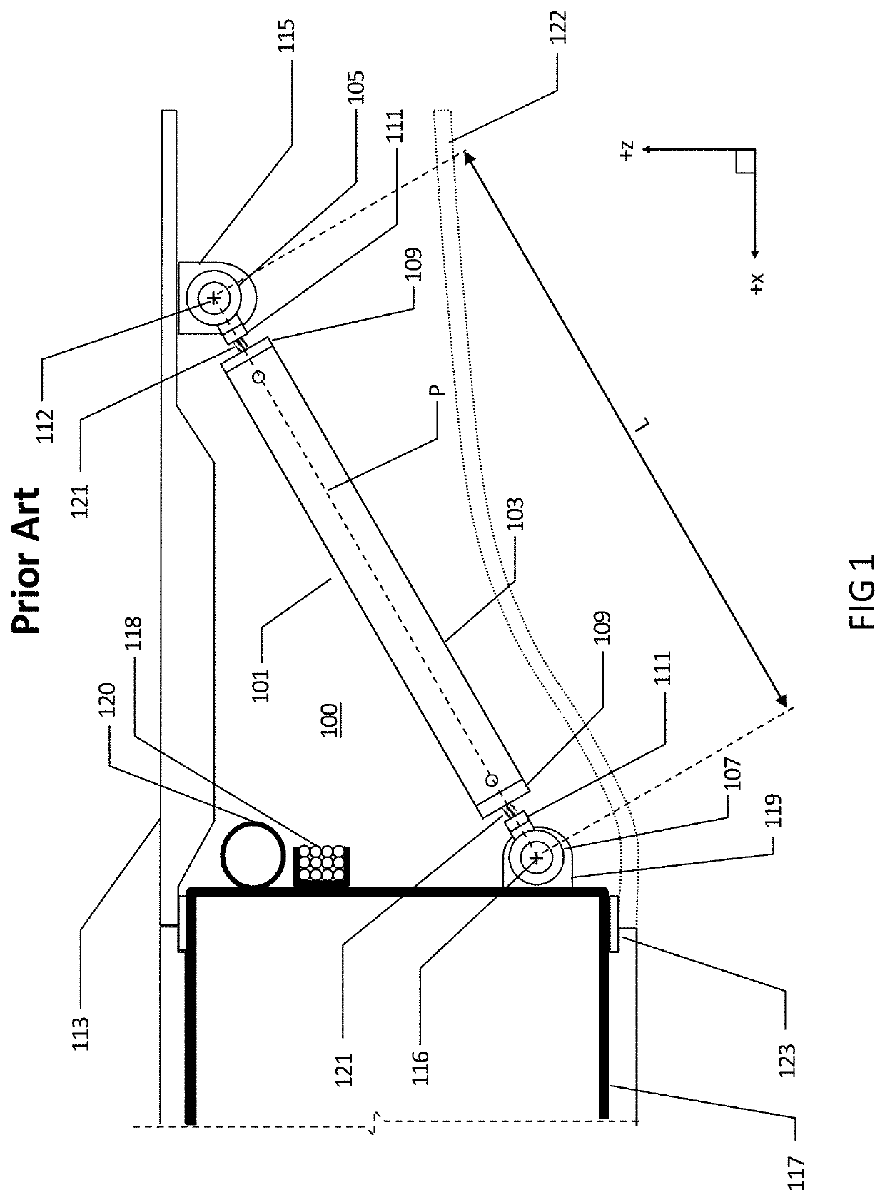
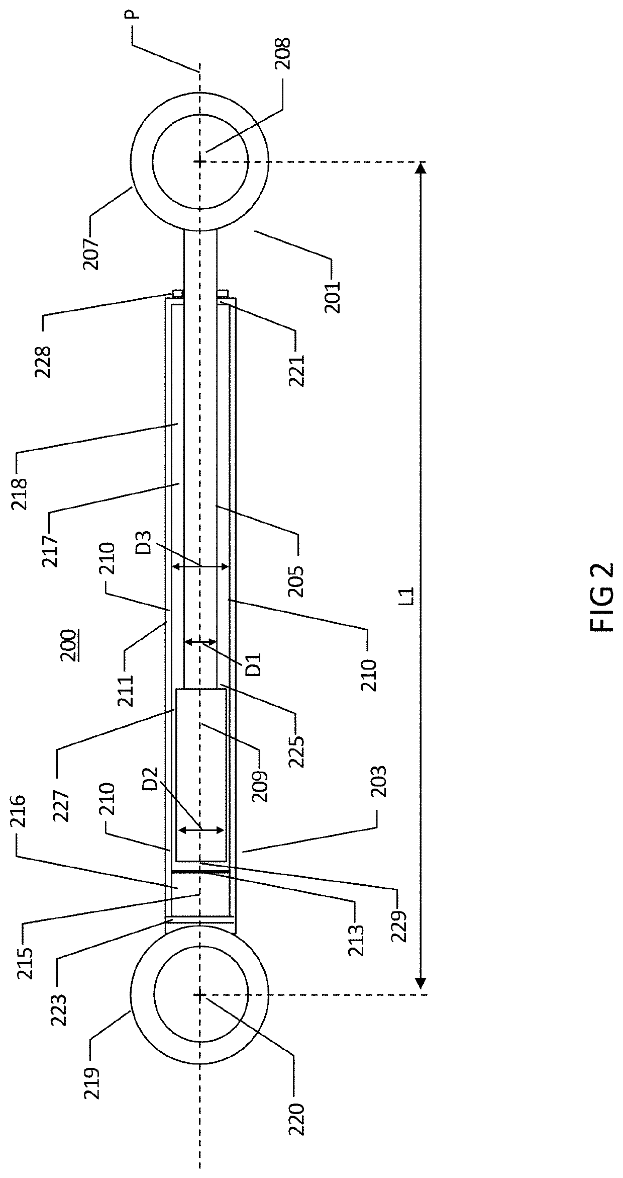
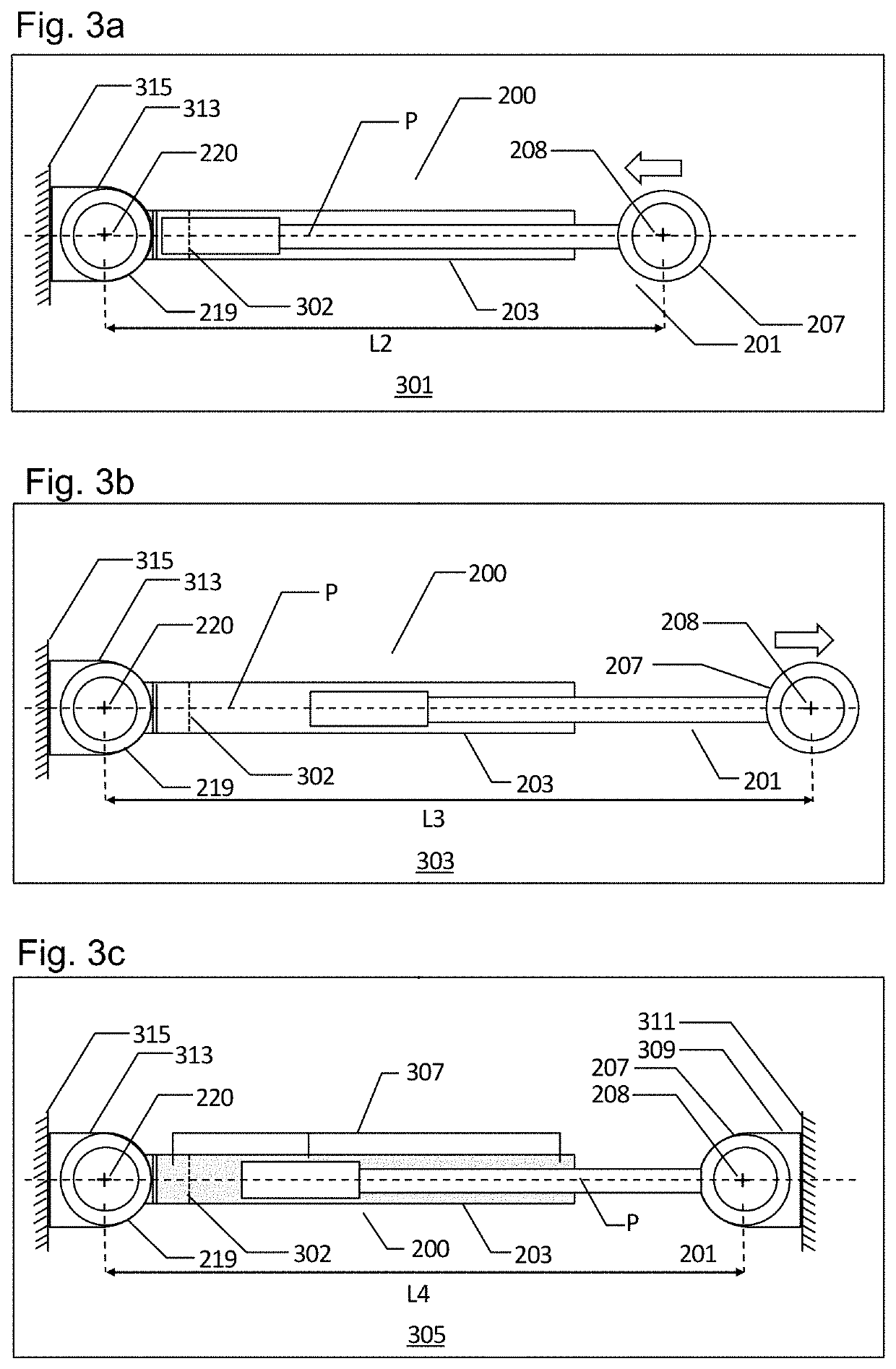
[0031]With reference to FIGS. 2 and 3a-3c, a connection rod 200 comprises a first connection element 201 and a second connection element 203. The primary functions of the connection rod 200 is the same as the prior art connection rod 101 of FIG. 1; that is, to connect components in an assembly and to provide adjustability during installation.

[0032]The first connection element 201 comprises a shaft 205 with a cross-sectional dimension D1 connected to a first connector 207 at a proximal end of the shaft 205. A distal end of the shaft 205 is connected to a piercing body 209 with a cross sectional dimension D2 at a distal end of the shaft 205. For the purpose of this description as a whole, a proximal end means the end of a connection element that is nearest to its point of attachment to a component, and a distal end means the end of a connection element that is furthest to its point of attachment to a component. The shaft 205 and piercing body 209 are cylindrical in cross-section revol...


PUM


Abstract

A connection rod comprising first and second connection elements. The first element comprises a shaft, a first connector at a shaft proximal end and a piercing body at a shaft distal end. The second element comprises a hollow casing with a fluid barrier therein, which, when intact, forms first and second reactive fluid material reservoirs, both within the casing. The second connection element comprises a second proximal end connector and a distal end inlet hole to the second reservoir. The piercing body fits within the casing and the shaft slidably engages the inlet hole such that the first element slides relative to the second element. The piercing body pierces the fluid barrier such that the reactive fluid materials mix between the reservoirs and react to form a reacted solid material restraining the piercing body within the casing to prevent relative sliding between the first and the second connection elements.

Description

CROSS-REFERENCES TO RELATED APPLICATIONS[0001]This application claims the benefit of the Great Britain patent application No. 1821307.4 filed on Dec. 31, 2018, the entire disclosures of which are incorporated herein by way of reference.FIELD OF THE INVENTION[0002]The present invention relates to a connection rod for connecting one or more aircraft components, an aircraft comprising a connection rod, and a method of installing a connection rod.BACKGROUND OF THE INVENTION[0003]It is known to assemble components on aircraft using threaded types of connection rods that are adjustable in length. Adjustability of the connection rod is required for installation of the connection rod between components in order to compensate for dimensional variations that may occur between the components. The adjustability therefore also enables different assemblies to meet specific dimensional requirements using the same connection rod design and is particularly useful for the assembly of large unitary co...

Claims


Application Information

Patent Timeline
Patent Type & Authority Applications(United States)
IPC IPC(8): B64C7/00B64F5/10
CPCB64F5/10B64C7/00F16B11/008B64C3/38B64C3/00B64C3/18F16C7/06
Inventor EHRING, BENJAMINLORENZ, FLORIAN
Owner AIRBUS OPERATIONS GMBH
Learn More