Machine learning method, machine learning system, and display system

a machine learning and display system technology, applied in the field of display devices, can solve problems such as noticeable boundary between panels and uneven display, and achieve the effect of improving the display quality of the display devi

Active Publication Date: 2020-07-09
SEMICON ENERGY LAB CO LTD
View PDF0 Cites 7 Cited by
  • Summary
  • Abstract
  • Description
  • Claims
  • Application Information

AI Technical Summary

Benefits of technology

[0024]According to one embodiment of the present invention, the display quality of the display device can be improved. A method of correct

Problems solved by technology

However, an increase in the display region of a display device produces the following problem: the influence of variation in the characteristics of transistors included in pixels, variation in the characteristics of display elements, or the like is increased, which results in

Method used


Image

  • Machine learning method, machine learning system, and display system
  • Machine learning method, machine learning system, and display system
  • Machine learning method, machine learning system, and display system

Examples


embodiment 1

[0067]In this embodiment, structure examples of a display system and a machine learning system and a machine learning method of one embodiment of the present invention and the like are described.

Structure Example of Display System

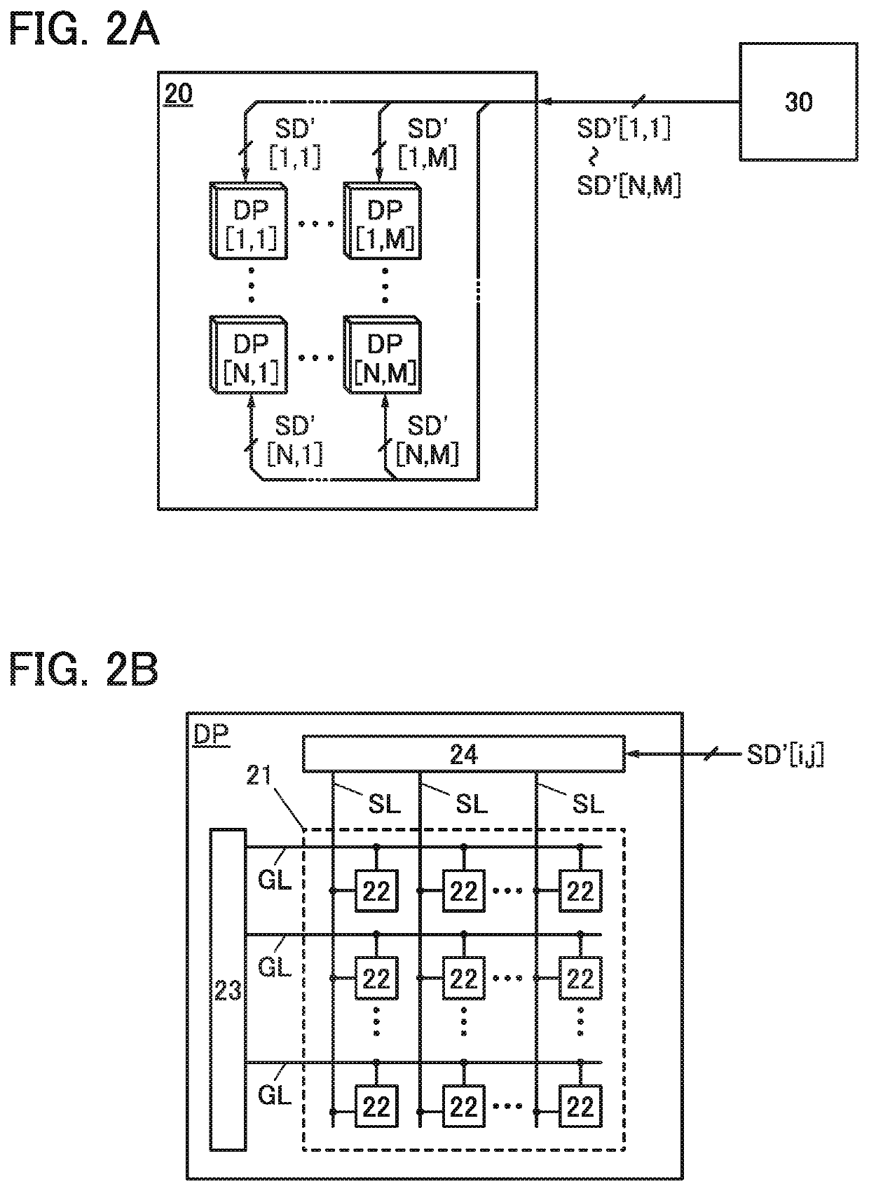
[0068]An example in which a display device included in the display system includes a plurality of display panels is given in the following description. Note that the display device may be formed of one display panel.

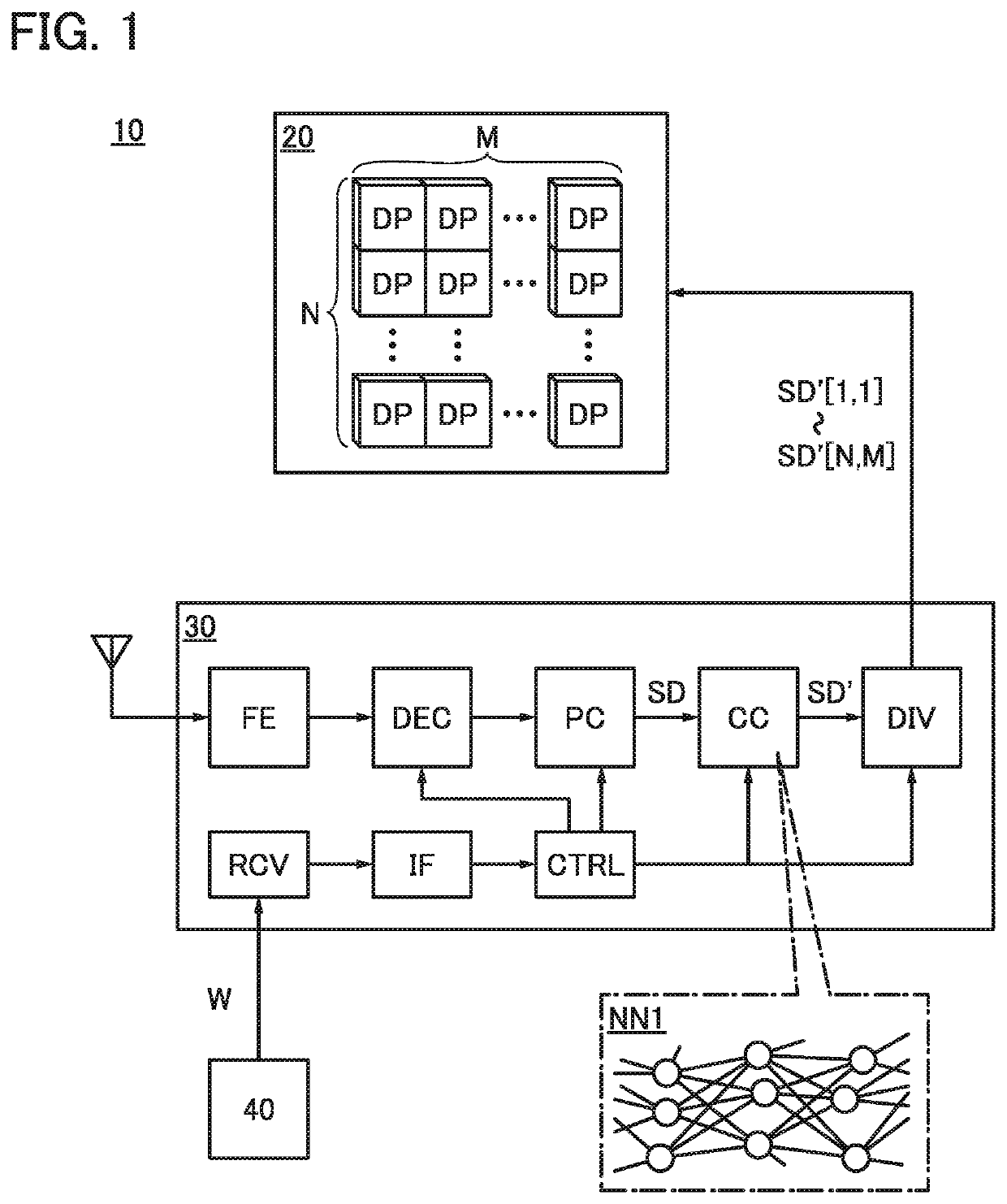
[0069]FIG. 1 illustrates a structure example of a display system 10. The display system 10 has a function of generating a signal for displaying a predetermined picture on the basis of data received from the outside and displaying the picture using the signal. The display system 10 includes a display device 20 and a signal generation portion 30.

[0070]Note that the display device 20 and the signal generation portion 30 can each be formed using a semiconductor device. Circuits included in the signal generation portion 30 can be integrated into one ...

modification example

[0179]A modification example of the above operation of the data generation portion 62 is described below.

[0180]In the method illustrated in FIG. 8 as an example, since the data SD3 is generated by adding the data SDc1 to the data SD1 corresponding to the original image, the gray level of a pixel in the generated data SD3 might exceed the gray level of the highest luminance (e.g., a gray level of 255 for 8-bit data) depending on the image of the data SD1. An example of a method that does not cause such a problem is described.

[0181]An example of a data generation method is described below with reference to FIG. 10.

[0182]First, as in the example illustrated in FIG. 8, the data SD2 is subtracted from the data SD1 to generate SDc1.

[0183]Here, the gray level of the pixel with the highest luminance in the data SDc1 is Vgc1max. In many cases, the pixel with Vgc1max is located in the region U.

[0184]Next, the data SDc2 is generated by an operation performed in such a manner that the gray leve...

embodiment 2

[0193]In this embodiment, a structure example of a semiconductor device that can be used in the neural networks described in the above embodiment is described.

[0194]As illustrated in FIG. 11A, a neural network NN can be formed of the input layer IL, the output layer OL, and the middle layer (hidden layer) HL. The input layer IL, the output layer OL, and the middle layer HL each include one or more neurons (units). Note that the middle layer HL may be one layer or two or more layers. A neural network including two or more middle layers HL can also be referred to as a deep neural network (DNN), and learning using a deep neural network can also be referred to as deep learning.

[0195]Input data is input to each neuron of the input layer IL, output signals of neurons in the previous layer or the subsequent layer are input to neurons of the middle layer HL, and output signals of neurons in the previous layer are input to neurons of the output layer OL. Note that each neuron may be connecte...


PUM


Abstract

To improve the display quality of a display device. To provide a method of correcting image data input to the display device. To provide a novel image correction method or an image correction system. Machine learning for a neural network correcting image data input to the display device is performed by the following method: second image data based on an image that is displayed on the display device by input of first image data to the display device is obtained; third image data is generated by obtaining a difference between the first image data and the second image data; fourth image data is generated by adding the first image data and the third image data; and a weight coefficient is updated so that output data obtained by input of the first image data to the neural network is close to the fourth image data.

Description

TECHNICAL FIELD[0001]One embodiment of the present invention relates to a display device. One embodiment of the present invention relates to an image correction technique. One embodiment of the present invention relates to a machine learning method and a system using the method.[0002]Note that one embodiment of the present invention is not limited to the above technical field. Examples of the technical field of one embodiment of the present invention disclosed in this specification and the like include a semiconductor device, a display device, a light-emitting device, a power storage device, a memory device, an electronic device, a lighting device, an input device, an input / output device, a driving method thereof, and a manufacturing method thereof.[0003]In this specification and the like, a semiconductor device means all devices that can operate by utilizing semiconductor characteristics. A transistor, a semiconductor circuit, an arithmetic device, a memory device, and the like are...

Claims


Application Information

Patent Timeline
IPC IPC(8): G09G5/37G06F3/14G06N3/08
CPCG09G2320/103G09G5/37G06N3/08G09G2300/026G09G2320/066G06F3/1446G09G2320/0233G09G3/20G09G3/3225G09G3/3648G09G2320/06G09G2340/0435G06T5/008G06N3/084G06N3/045
Inventor OKAMOTO, YUKI
Owner SEMICON ENERGY LAB CO LTD
Why Eureka
Try Eureka