
Angled power pin alignment and crimping fixture

Active Publication Date: 2020-07-23
ANDERSON DAVID +2
View PDF0 Cites 0 Cited by
  • Summary
  • Abstract
  • Description
  • Claims
  • Application Information

AI Technical Summary

Benefits of technology

The present invention provides a power pin alignment and crimping fixture that allows for easy and precise crimping of power pins to conductors of an electrical submersible pump cable. The fixture features a plurality of channels that are angled in a way that each channel is aligned with a corresponding side edge of a symmetrical shape. The crimping process involves inserting power pins into the channels, stripping back armor and insulation, placing the conductors within the power pins, and then crimping the power pins to the conductors. The technical effects of this invention include efficient and accurate crimping, simplified procedure, and improved reliability of power transmission.

Problems solved by technology

This manipulation of the insulated conductors increases the risk of damaging them which could potentially cause an electrical failure.

Method used


Image

  • Angled power pin alignment and crimping fixture
  • Angled power pin alignment and crimping fixture
  • Angled power pin alignment and crimping fixture

Examples


Embodiment Construction

[0018]The following detailed description is of the best currently contemplated modes of carrying out exemplary embodiments of the invention. The description is not to be taken in a limiting sense, but is made merely for the purpose of illustrating the general principles of the invention, since the scope of the invention is best defined by the appended claims.

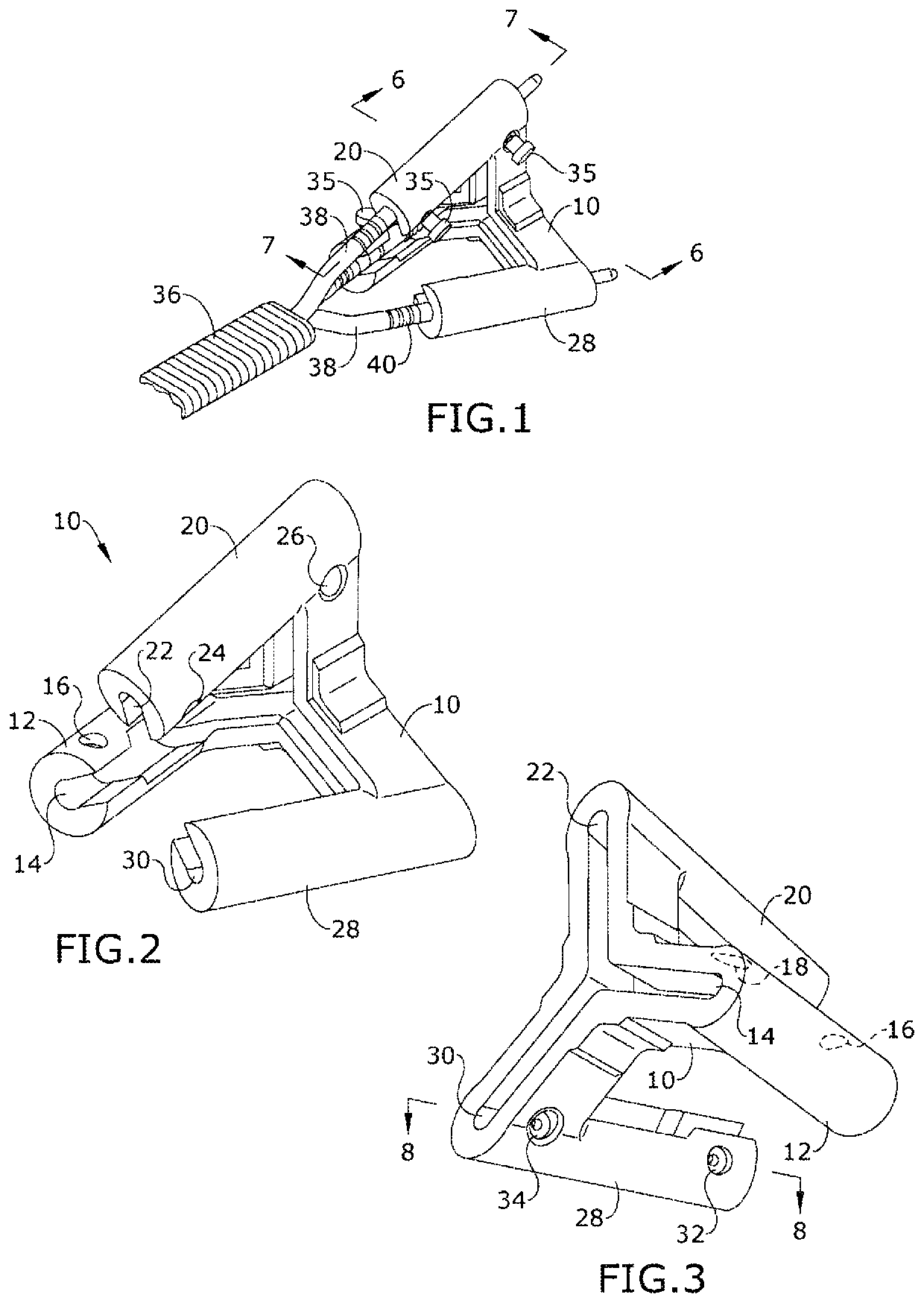
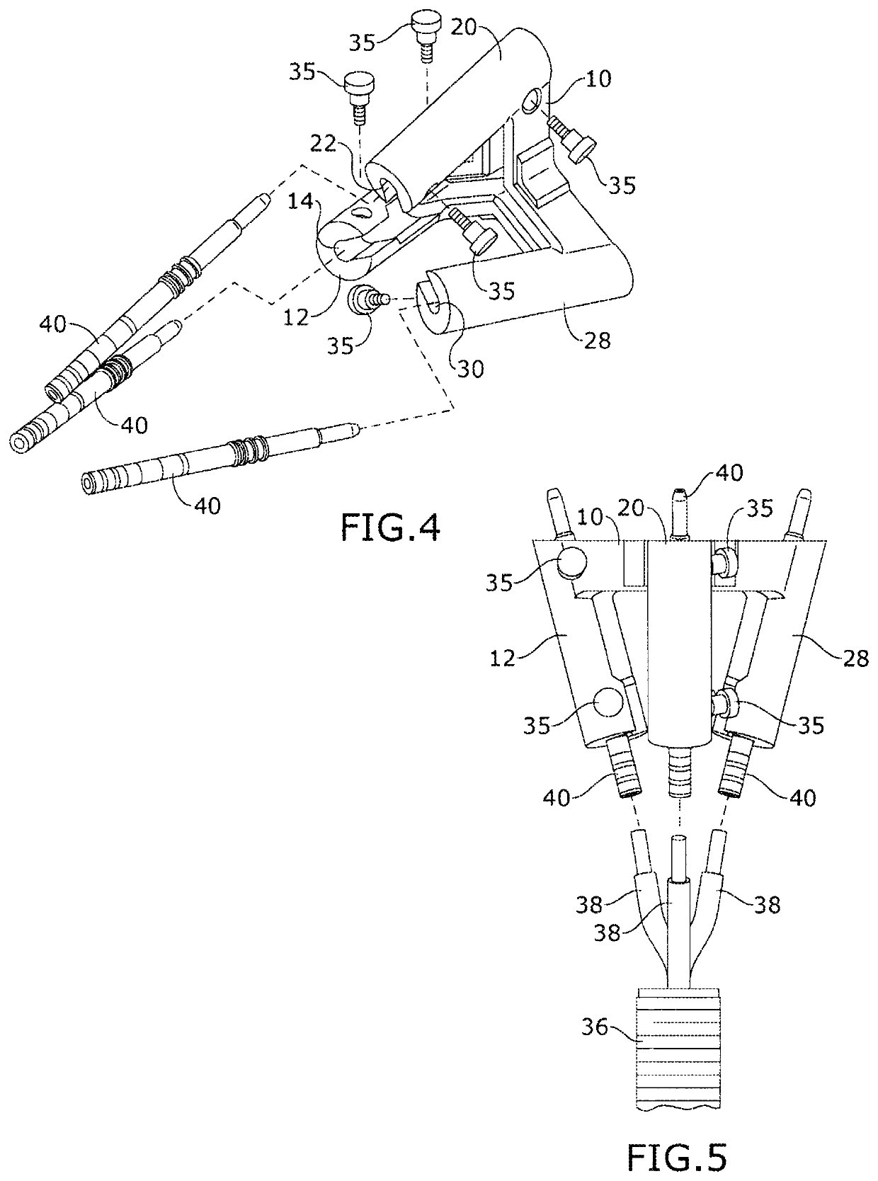
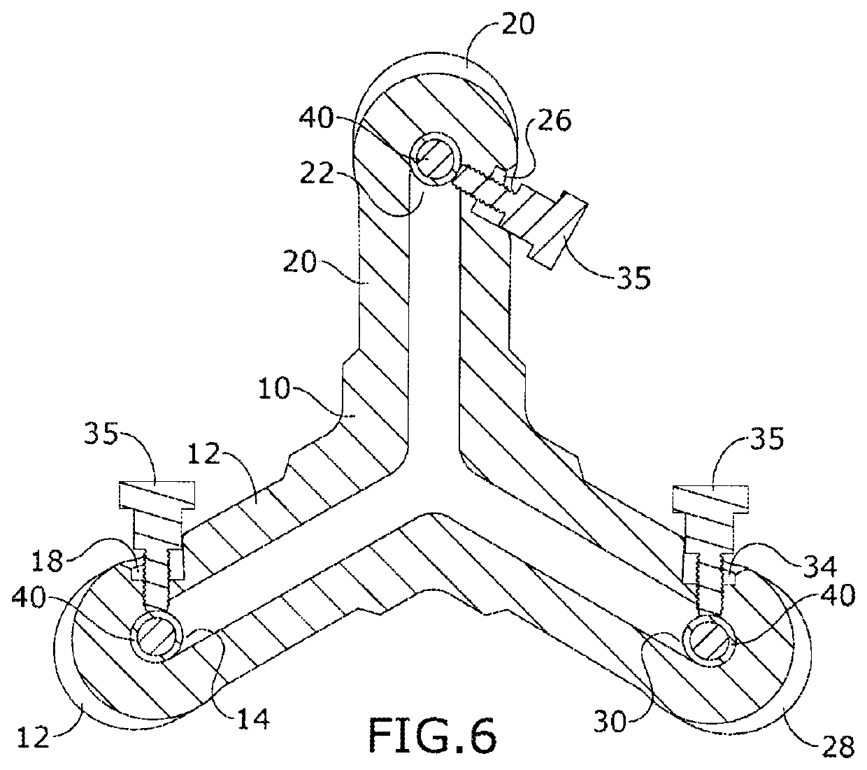
[0019]Referring to FIGS. 1 through 9, the present invention includes a power pin alignment and crimping fixture having a fixture body 10. The fixture body 10 includes a plurality of channels 14, 22, 30 each having a first open end and a second open end. The plurality of channels 14, 22, 30 are disposed at an angle diverging away from one another in a direction from the first open end to the second open end such that each of the plurality of channels 14, 22, 30 are disposed along a corresponding side edge of a symmetrical shape.

[0020]The fixture body 10 of the present invention may include a plurality of fixture arms 12, 20, 28 a...


PUM


Abstract

A power pin alignment and crimping fixture having a fixture body. The fixture body includes a plurality of channels each having a first open end and a second open end. The plurality of channels are disposed at an angle diverging away from one another in a direction from the first open end to the second open end such that each of the plurality of channels are disposed along a corresponding side edge of a symmetrical shape.

Description

CROSS-REFERENCE TO RELATED APPLICATION[0001]This application claims the benefit of priority of U.S. provisional application No. 62 / 794,166, filed Jan. 18, 2019, the contents of which are herein incorporated by reference.BACKGROUND OF THE INVENTION[0002]The present invention relates to a method and apparatus for crimping and, more particularly, to an angled power pin alignment and crimping fixture.[0003]In the oil and gas industry, electrical submersible pumps are utilized to pump crude oil. In many cases, electrical connectors are attached to lengths of electrical submersible pump (ESP) cables and used to provide power to the pumps. Within the method of attaching the electrical connectors to the ESP cable, special pins are often attached, or crimped onto the electrically insulated conductors of the ESP cable. The position of the power pins after being crimped is critical to properly attach the ESP cable to the associated electrical connector. The conductors within ESP cables are typ...

Claims


Application Information

Patent Timeline
IPC IPC(8): H01R13/207H01R13/58E21B43/12
CPCH01R13/5808H01R13/207E21B43/128H01R43/0421H01R43/28H01R13/533
Inventor ANDERSON, DAVIDKEEFER, MYLESLE, LARRY
Owner ANDERSON DAVID
Learn More