Method for producing polycrystalline silicon

a technology of polycrystalline silicon and siemens method, which is applied in the direction of silicon compounds, coatings, chemistry apparatus and processes, etc., can solve the problems of severe environmental exposure of the heater, heater deterioration, and carbon contamination in the polycrystalline silicon produced by the siemens method, and achieve high efficiency, high quality polycrystalline silicon, and reduced carbon contamination.

Pending Publication Date: 2020-07-30
SHIN ETSU CHEM IND CO LTD
View PDF0 Cites 0 Cited by
  • Summary
  • Abstract
  • Description
  • Claims
  • Application Information

AI Technical Summary

Benefits of technology

[0026]According to the present invention, the level of carbon contamination in polycrystalline silicon produced by the Siemens method can be reduced, and high-quality polycrystalline silicon can be produced at high efficiency.

Problems solved by technology

Accordingly, the carbon heater for heating is exposed to a severe environment (high-temperature and high-speed gas flow) in the reactor although the reactor is no longer used for the reaction, and deteriorates severely.
The heater deteriorates after a single use (one batch of deposition reaction) in many cases.
It is difficult to use the heater for a plurality of times, which is one factor to increase the cost of polycrystalline silicon production.
In addition, the carbon heater for heating remains left in the deposition space of polycrystalline silicon, and thus, the heater may become a source of carbon contamination of polycrystalline silicon to be deposited.
Particularly in a reactor designed for highly-effective deposition reaction, there is a problem in that carbon contamination from the carbon heater for heating is likely to occur because deposition reaction proceeds at high pressure and high temperature.
This method, which is a method for heating from the outside of the reactor, has for example the following drawbacks: use of a special and expensive apparatus is required (Patent Literature 4: Japanese Patent Laid-Open No. 9-241099); and a portion of the wall of the reactor is required to be produced with transparent quartz having strength lower than that of steel (Patent Literature 5: Japanese Patent Laid-Open No. 2001-278611).
Problematically, this is not preferable for safety reasons as a reactor for carrying out reaction under a high pressure.

Method used


Image

  • Method for producing polycrystalline silicon
  • Method for producing polycrystalline silicon
  • Method for producing polycrystalline silicon

Examples


examples

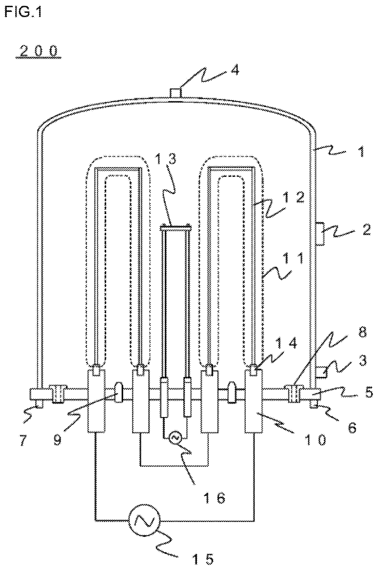
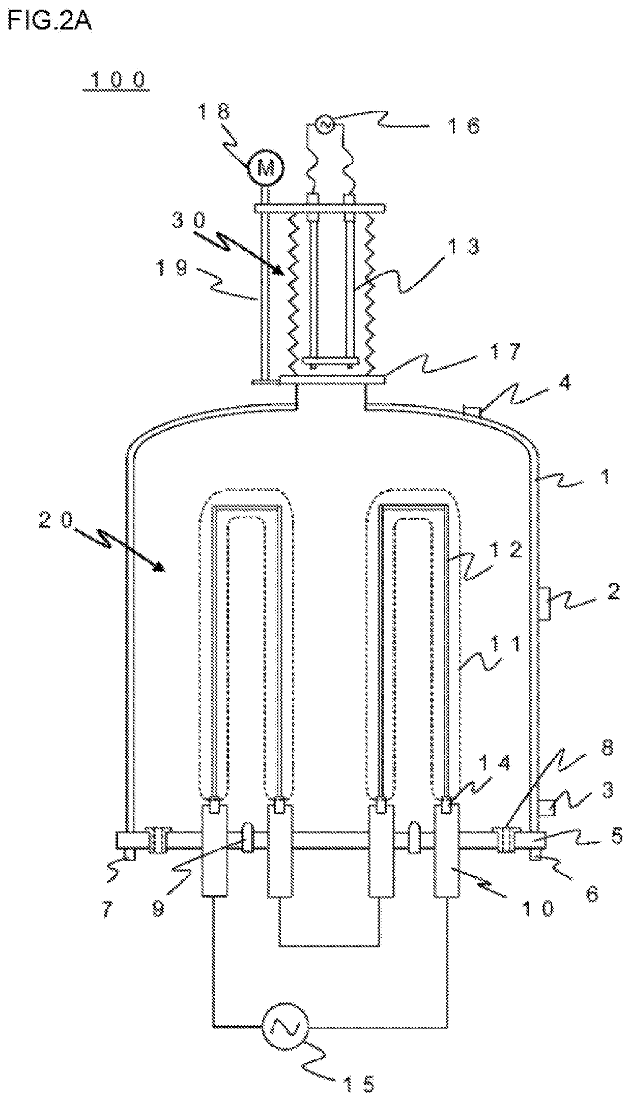
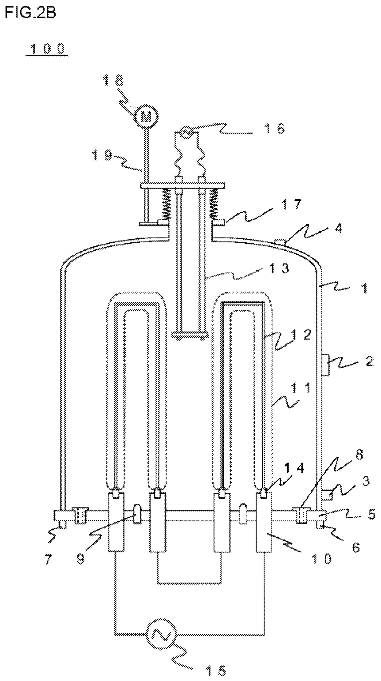
[0058]In the present example, in the case where polycrystalline silicon was deposited using a reactor having a structure shown in FIGS. 2A to B, (a) the concentration of methane contained in exhaust gas during reaction and (b) the concentration of carbon contained in grown polycrystalline silicon were measured (Example: batch 1). For comparison, in the case where polycrystalline silicon was grown using a reactor having a conventional structure shown in FIG. 1, (a) the concentration of methane contained in exhaust gas during reaction and (b) the concentration of carbon contained in grown polycrystalline silicon were also measured (Comparative Example: batch 2).

[0059]FIG. 3 is a graph showing the deposition reaction time dependency of a CH4 concentration in the exhaust gas. With respect to Example, the methane concentration in the exhaust gas were equivalent to or lower than the lower detection limit (less than 0.100 volppm) through the deposition reaction step (72 hours). In contrast...


PUM

PropertyMeasurementUnit
temperatureaaaaaaaaaa
pressureaaaaaaaaaa

Abstract

A reactor 200 according to the present invention includes a heater storage section serving as a space section capable of accommodating a carbon heater for initial heating of silicon core wires. A carbon heater 13 is loaded in a deposition reaction space 20 in the reactor 200 only when necessary for initial heating of silicon core wires 12. After initial heating of the silicon core wires 12 is finished, the carbon heater 13 is unloaded from the deposition reaction space to the heater storage section 30. As a result, the carbon heater 13 is not unduly damaged in the reactor any longer and its deterioration is reduced. In addition, because of reduction in reaction with hydrogen gas in the reactor, the generation of methane is reduced, and thus carbon contamination of polycrystalline silicon is reduced.

Description

CROSS-REFERENCE TO RELATED APPLICATION[0001]This application is a divisional of U.S. application Ser. No. 15 / 741,356, filed on Jan. 2, 2018, and wherein U.S. application Ser. No. 15 / 741,356 is a national stage application filed under 35 U.S.C. § 371 of International Application No. PCT / JP2016 / 071674, filed Jul. 25, 2016, which is based upon and claims the benefit of priority of the prior Japanese Patent Application No. 2015-148989, filed on Jul. 28, 2015, the entire contents of which are incorporated herein by reference.TECHNICAL FIELD[0002]The present invention relates to relates to a technique for producing polycrystalline silicon, more specifically to a technique suitable for reducing the concentration of carbon contained in polycrystalline silicon produced by a Siemens method.BACKGROUND ART[0003]Polycrystalline silicon is a raw material for single-crystal silicon substrates for producing semiconductor devices or substrates for producing a solar cell. In general, polycrystalline ...

Claims


Application Information

Patent Timeline
Patent Type & Authority Applications(United States)
IPC IPC(8): C01B33/035C23C16/24
CPCC01B33/035C23C16/24
Inventor KUROSAWA, YASUSHINETSU, SHIGEYOSHIHOSHINO, NARUHIRO
Owner SHIN ETSU CHEM IND CO LTD
Why Eureka
Try Eureka