Power supply device for electric vehicle

a technology for power supply devices and electric vehicles, applied in the direction of electric variable regulation, process and machine control, instruments, etc., can solve problems such as unintended increase in power loss in the power supply of electric vehicles, and achieve the effect of inhibiting an increase in power loss

Active Publication Date: 2020-07-30
KK TOSHIBA +1
View PDF0 Cites 2 Cited by
  • Summary
  • Abstract
  • Description
  • Claims
  • Application Information

AI Technical Summary

Benefits of technology

[0006]An objective of the present invention is to provide a power supply for electric vehicle capable of inhibiting an increase in a power loss occurring due to a variation in a power amount supplied to a load.
[0007]According an embodiment of the present invention, a power supply for electric vehicle includes a resonant inverter, a transformer, an influence inhibitor, and a control unit. The resonant inverter includes a first resonant capacitor included in a resonant circuit and a switching element that cuts off a current flowing in the resonant circuit, is supplied with direct-current power from a power supply, and generates first alternating-current power from the direct-current power through resonance of the resonant circuit and periodic switching of the switching element. The transform

Problems solved by technology

Therefore, an unintended increase in a power loss in the

Method used


Image

  • Power supply device for electric vehicle
  • Power supply device for electric vehicle
  • Power supply device for electric vehicle

Examples


first embodiment

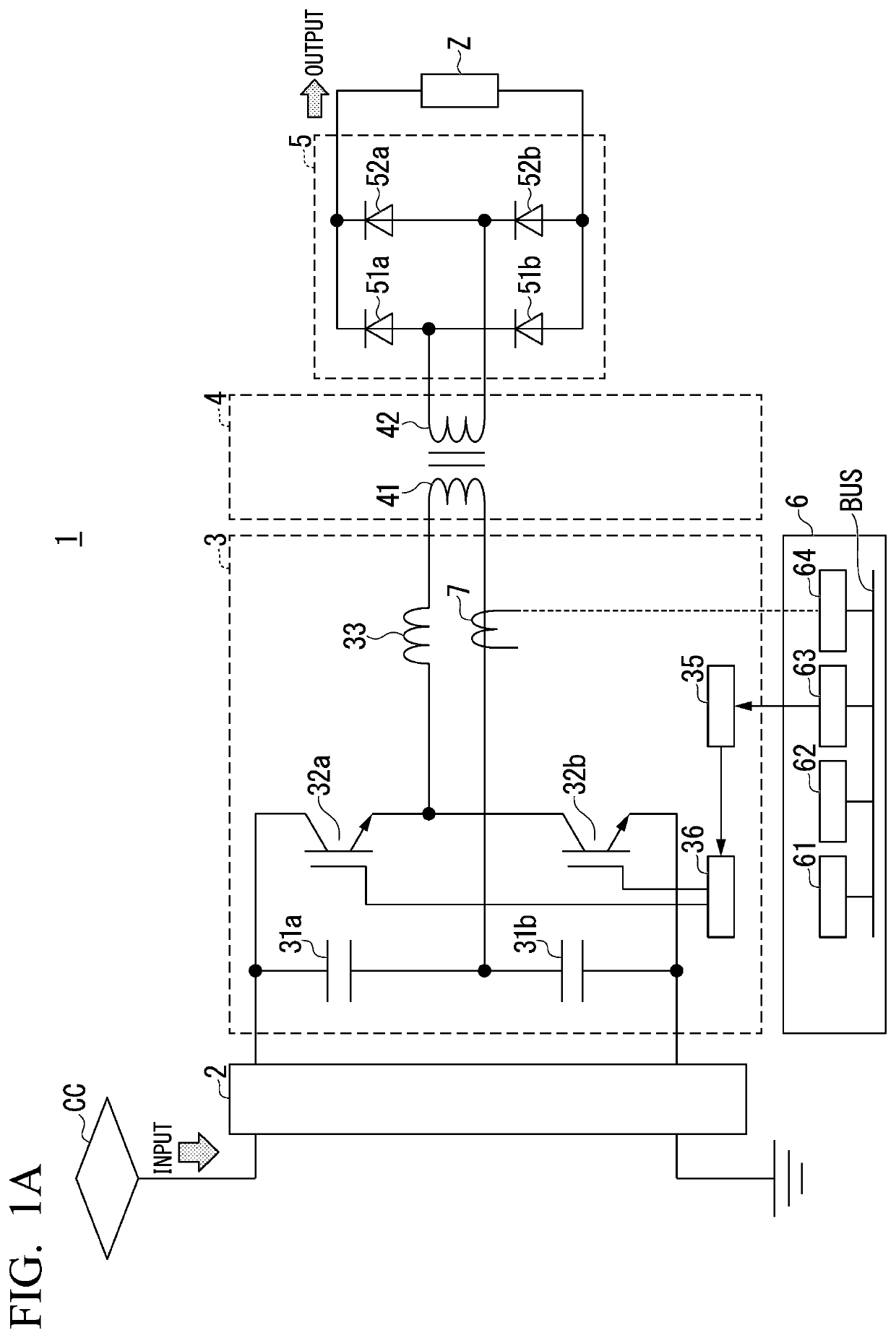
[0024]FIG. 1A is a diagram illustrating an overall configuration of a power supply for electric vehicle according to a first embodiment. The power supply 1 for electric vehicle is connected in series to a current path between a current collector CC supplied with power from an overhead wire (feeder) F (not illustrated) and a wheel W (not illustrated) grounded via a line R (not illustrated). A pole that has substantially the same potential as a pole on the side of the line R and the wheel W in FIG. 1A is indicated as a ground pole.

[0025]The power supply 1 for electric vehicle includes, for example, a power conversion circuit 2, a resonant inverter 3, a transformer 4, a rectifier 5 (rectifier circuit), a control unit 6, and a current detector 7 (a first current detector). Reference sign Z denotes a load.

[0026]The power conversion circuit 2 is connected to the rear stage of the current collector CC and converts power collected by the current collector CC into direct-current power with a...

first modified example

(First Modified Example of First Embodiment)

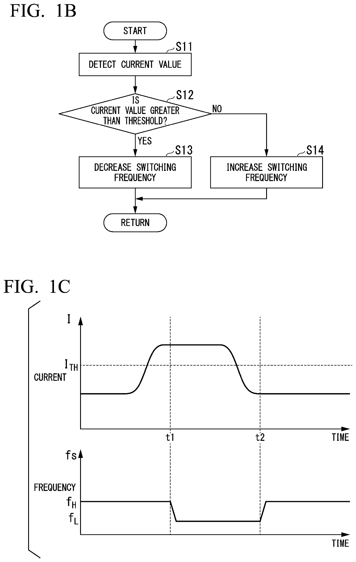
[0065]The resonant inverter 3 according to the first embodiment adjusts the switching frequency of the resonant inverter to a pre-decided switching frequency in a fixed or semi-fixed manner. Instead of this, in a first modified example, an instance in which a switching frequency of a resonant inverter is adjusted to an optimized frequency will be described.

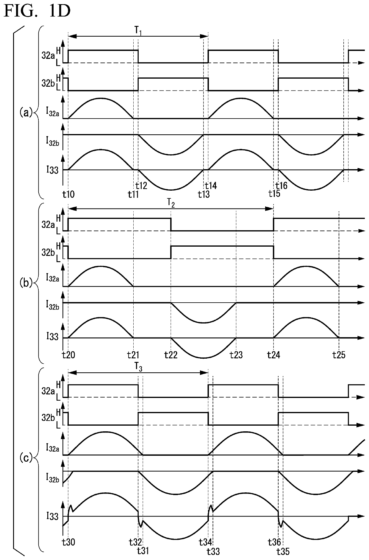
[0066]In the case of the resonant inverter, by forming a current waveform as a waveform closer to a sinusoidal wave, it is possible to further improve efficiency. Accordingly, the control unit 6 finds an upper limit of the resonant frequency at which the switching of the switching elements 32a and 32b is the soft switching, forms a waveform of a current flowing to the primary side of the transformer 4 as a waveform closer to a sinusoidal wave, and outputs the waveform.

[0067]For example, the power supply 1 for electric vehicle includes the current detector 7 that detects a current flowing...

second modified example

(Second Modified Example of First Embodiment)

[0069]The resonant inverter 3 according to an embodiment is an example of a half bridge type voltage inverter. The resonant inverter 3 is not limited to the resonant inverter illustrated in FIG. 1A. Instead of this, for example, a full bridge type voltage inverter or current inverter may be used. In the case of the current inverter, the control unit 6 can measure a voltage instead of measuring a current, as described above, and can perform the control similarly based on the voltage.


PUM


Abstract

A resonant inverter of a power supply for electric vehicle includes a first resonant capacitor and a switching element cutting off a current flowing in a resonant circuit and generates first alternating-current power from direct-current power. The transformer is included in a part of the resonant circuit, supplies the first alternating-current power generated by the resonant inverter to a first winding, and supplies second alternating-current power after conversion of the first alternating-current power to a load from a second winding. A control unit confines a difference between a resonant frequency of the resonant circuit and a switching frequency of the switching element to a predetermined range to cause that a current flowing in switching of the switching element to at least the first winding or the second winding is equal to or less than a predetermined value and to cause the resonant inverter to perform soft switching.

Description

TECHNICAL FIELD[0001]Embodiments of the present invention relate to a power supply for electric vehicle.[0002]Priority is claimed on Japanese Patent Application No. 2017-212151, filed Nov. 1, 2017, the content of which is incorporated herein by reference.BACKGROUND ART[0003]There are power supply for electric vehicles that include resonant inverters. Values of resonant frequencies of resonant circuits of the resonant inverters are determined mainly depending on capacitances of capacitors and inductances of transformers. When semiconductor switching elements cutting off currents flowing in the resonant circuits of the resonant inverters are caused to perform soft switching, actual resonant frequencies of the resonant circuits are set to be higher than frequencies for cutting off the semiconductor switching elements (switching frequencies) periodically. When the actual resonant frequencies of the resonant circuits are lower than the switching frequencies, the semiconductor switching e...

Claims


Application Information

Patent Timeline
IPC IPC(8): H02M7/537H02M3/335H02M1/08B60L5/00
CPCB60L5/00H02M2001/0058H02M1/08H02M7/537H02M3/33569H02M2001/0009H02M2007/4815Y02T10/72B60L9/00B60L9/005B60L2210/40H02M1/0058H02M3/015H02M1/0009H02M3/33571H02M7/4815
Inventor SHIRASAWA, YUKIMAKI, YASUOMI
Owner KK TOSHIBA
Why Eureka
Try Eureka