
Display panel and display device

a display panel and display device technology, applied in the field of display technology, can solve the problems low yield, and high cost of large-scale evaporation process, and achieve the effect of preparing high-precision metal masks (fmm)

Active Publication Date: 2020-08-06
FUZHOU BOE OPTOELECTRONICS TECH CO LTD +1
View PDF0 Cites 8 Cited by
  • Summary
  • Abstract
  • Description
  • Claims
  • Application Information

AI Technical Summary

Benefits of technology

The patent text discusses the advantages and challenges of OLED display technology, especially in terms of manufacturing large-sized screens. The technical problem addressed in the patent text is the difficulty of applying oxide technology to manufacture large-sized OLED screens, which results in technical problems such as low yields and high costs. The text proposes a solution to address this problem by applying low-temperature poly-silicon technology to manufacture large-sized OLED screens, which can provide higher yields and reduce costs.

Problems solved by technology

At present, small-sized OLED screens have been manufactured in mass production; however, in contrast to small-sized and medium-sized OLED screens applying low-temperature poly-silicon technology, large-sized OLED screens applying oxide technology encounters a variety of technical difficulties through its popularization.
In relevant art, a large-scale organic electroluminescent layer is mainly formed by an evaporation process; however, a large-scale evaporation process has relatively high cost and relatively low yield, and requires to prepare high-precision metal mask (FMM).

Method used


Image

  • Display panel and display device
  • Display panel and display device
  • Display panel and display device

Examples


Embodiment Construction

[0054]In order to set forth purposes, technical solutions and advantages of the disclosure more clearly, exemplary embodiments will now be described in detail with reference to the accompanying drawings. It should be understood that the following description of embodiments is intended to explain and clarify a general concept of the disclosure, and should not be construed as a limitation of the disclosure. In the specification and drawings, same or similar reference numerals refer to same or similar parts or components. For clarity, the drawings are not necessarily drawn to scale, and some known parts and structures may be omitted from the drawings.

[0055]Unless otherwise defined, the technical or scientific terms used in the disclosure shall be the general meaning understood by those skilled having general skills in the field to which the disclosure belongs. Words “first”, “second” and the like used in the present disclosure merely intend to distinguishing different components, rathe...


PUM


Abstract

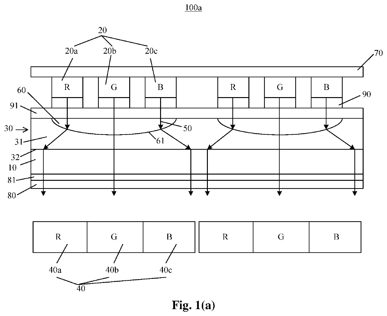
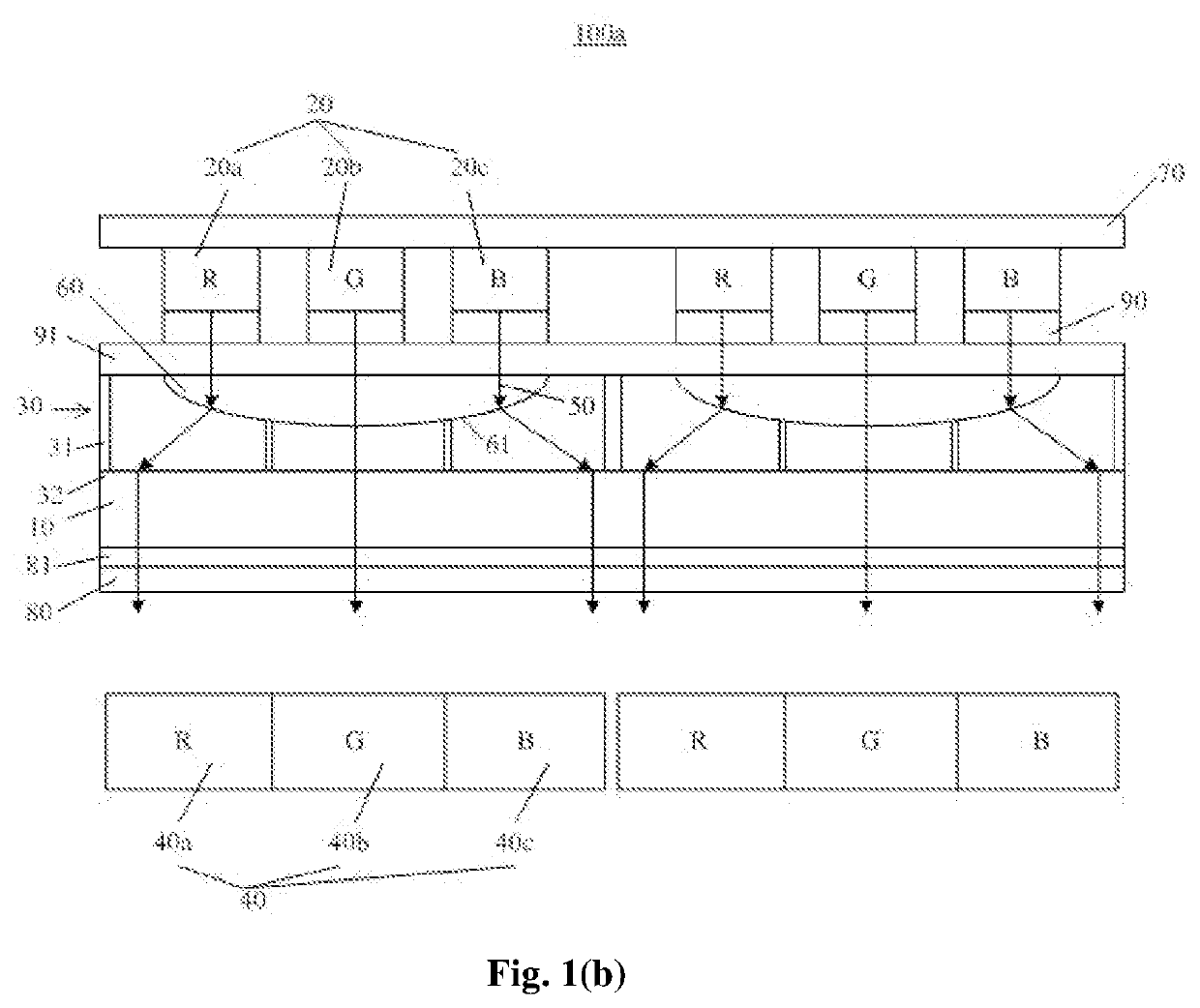
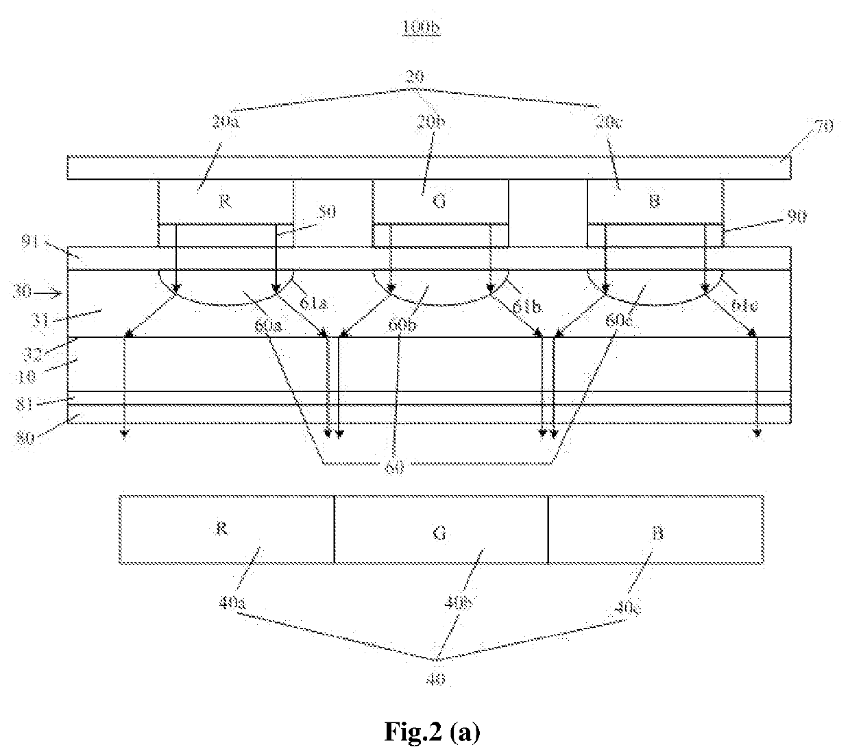
A display panel which is configured to display images is provided in embodiments of the disclosure, each image including a plurality of image pixels and each image pixel including a plurality of sub-pixels of different colors, respectively, the display panel including: a base substrate; and a plurality of sub-beam generation components on the base substrate, each sub-beam generation component being configured to generate at least one sub-pixel in at least one image pixel of the plurality of image pixels and including: a group of light-emitting units comprising at least one light-emitting unit and corresponding to at least one sub-pixel; and a beam-expanding layer, which is arranged on a light emergent side of the group of light-emitting units and configured to expand light beams emitted from the group of light-emitting units; an orthogonal projection of the beam-expanding layer on the base substrate at least partially overlapping with an orthogonal projection of the group of light-emitting units on the base substrate.

Description

CROSS-REFERENCE TO RELEVANT DISCLOSURE[0001]This application is a Section 371 National Stage Application of International Application No. PCT / CN2019 / 097259, filed on Jul. 23, 2019, entitled “DISPLAY PANEL AND DISPLAY DEVICE”, which published as WO 2020024848 A1, on Feb. 6, 2020, and claims priority to Chinese Patent Application Disclosure No. 201810856018.X filed on Jul. 31, 2018, in the China National Intellectual Property Administration, the contents of which are incorporated herein by reference in their entireties.BACKGROUND OF THE DISCLOSUREField of the Disclosure[0002]Embodiments of the present disclosure generally relate to the technical field of display technology, and in particular, to a display panel and a display device.Description of the Relevant Art[0003]Organic light-emitting diodes (OLEDs) may be a future direction of display technology which has attracted much attention. OLED display technology has advantages such as self-illumination, all-solid-state, relatively fine...

Claims


Application Information

Patent Timeline
IPC IPC(8): H01L51/52H01L27/32
CPCH01L2251/5307H01L27/322H01L51/5275H01L2251/5315H10K59/35H10K59/879G02B3/0056G02B3/0062H10K59/38H10K2102/3023H10K50/858H10K2102/3026
Inventor PAN, WANPINGZHU, AIHUAJIA, XIAOBOYU, HAILONG
Owner FUZHOU BOE OPTOELECTRONICS TECH CO LTD
Learn More