Photovoltaic assembly

a photovoltaic and assembly technology, applied in the direction of basic electric elements, electrical equipment, semiconductor devices, etc., can solve the problems of inconsistent energy conversion efficiency of solar panels, reduction of brightness at the periphery of solar panels,

Inactive Publication Date: 2009-01-15
HON HAI PRECISION IND CO LTD
View PDF4 Cites 1 Cited by
  • Summary
  • Abstract
  • Description
  • Claims
  • Application Information

AI Technical Summary

Benefits of technology

[0008]A photovoltaic assembly is provided. In one embodiment, the photovoltaic assembly includes a photovoltaic panel and a light leveling element. The photovoltaic panel includes a plurality of spaced photosensitive regions for receiving and converting light energy into electric energy. The light leveling element is disposed above the photovoltaic panel. The light leveling element includes a base, a plurality of first lenses and a plurality of second lenses. The first lenses are arranged on a central portion of the base. The second lenses are disposed on a peripheral portion of the base. The first and the second lenses are vertically aligned with the respective photosensitive regions. The refraction indices of the first lenses are less than that of the second lenses.

Problems solved by technology

However, when the light passes through the converging lens onto the solar panel of the solar cell, vignetting is unintentionally and undesirably generated and causes a reduction of brightness at the periphery portion of the solar panel.
Thus, energy conversion efficiency of the solar panel is inconsistent.

Method used


Image

  • Photovoltaic assembly
  • Photovoltaic assembly
  • Photovoltaic assembly

Examples


Embodiment Construction

[0016]Reference will now be made to the drawings to describe embodiments of the present photovoltaic assembly in detail.

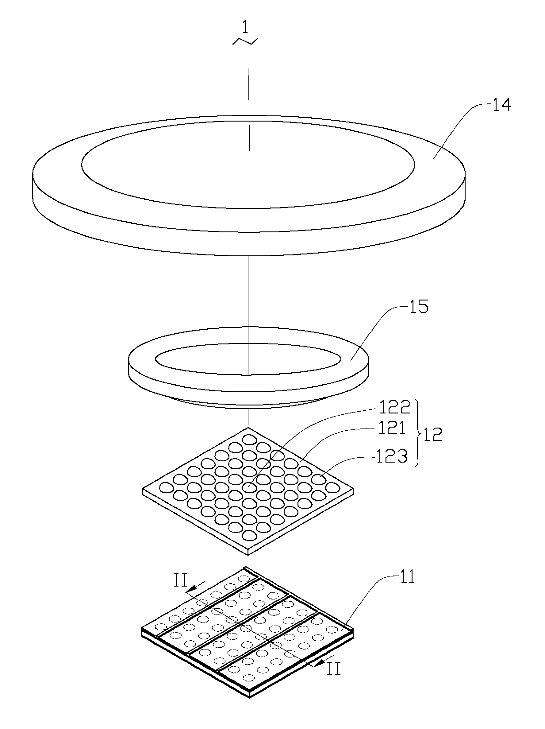
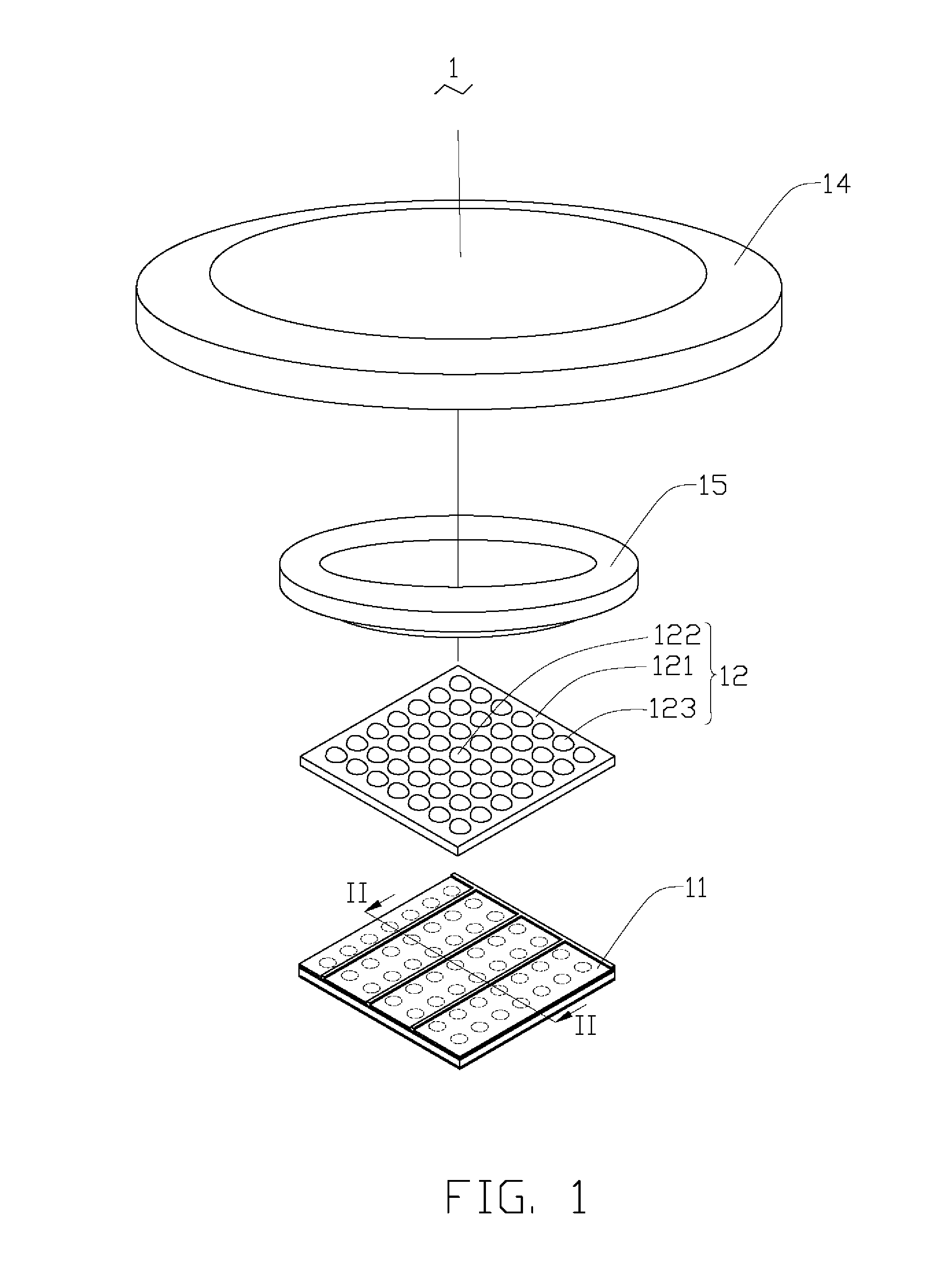
[0017]Referring to FIG. 1, a photovoltaic assembly 1 includes a photovoltaic panel 11 and a light leveling element 12. The light leveling element 12 is disposed above the photovoltaic panel 11.

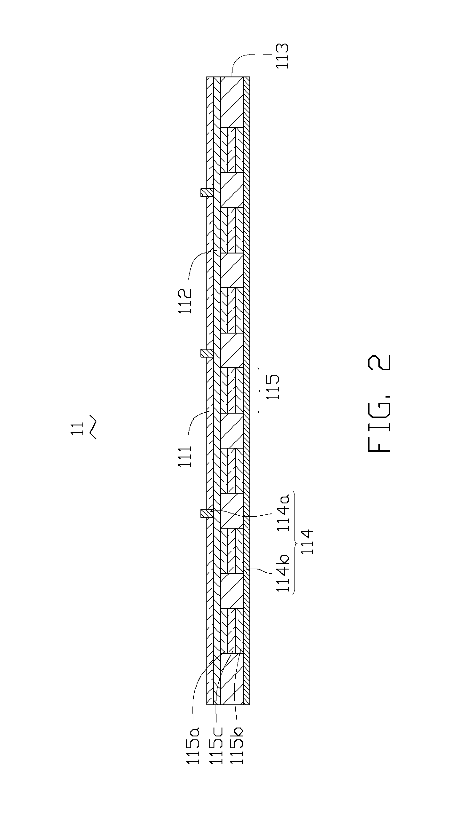
[0018]Referring to FIG. 2, the photovoltaic panel 11 includes a light-permeable substrate 111, an electrically conductive layer 112, a photovoltaic layer 113 and a pair of electrodes 114. The electrically conductive layer 112 is laminated on the light-permeable substrate 111 and the photovoltaic layer 113 is laminated on the electrically conductive layer 112. The light-permeable substrate 111 is made of glass and the electrically conductive layer 112 is made of indium tin oxide (ITO). The pair of electrodes 114 includes a front electrode 114a and a back electrode 114b disposed at opposite sides of the photovoltaic layer 113. In the present embodiment, the electrodes 114 are m...


PUM


Abstract

A photovoltaic assembly includes a photovoltaic panel and a light leveling element. The photovoltaic panel includes a plurality of spaced photosensitive regions for receiving and converting light energy into electric energy. The light leveling element is disposed above the photovoltaic panel. The light leveling element includes a base, a plurality of first lenses and a plurality of second lenses. The first lenses are arranged on a central portion of the base. The second lenses are disposed on a peripheral portion of the base. The first and the second lenses are vertically aligned with the respective photosensitive regions. The refraction indices of the first lenses are less than that of the second lenses.

Description

BACKGROUND[0001]1. Technical Field[0002]The invention relates to energy conversion assemblies, and particularly to a photovoltaic assembly.[0003]2. Description of Related Art[0004]Currently, solar energy is considered a renewable and clean energy source, and can also be used as an alternative source of energy other than fossil fuel. Solar energy is generally produced by photovoltaic cells, as known as solar cells. The photovoltaic cell or the solar cell is a device that converts light into electrical energy using the photoelectric effect.[0005]Generally, the solar cell includes a large-area p-n junction made from silicon. Particularly, the solar cell generally includes a layer of n-type silicon, a layer of p-type silicon, and a pair of electrodes. The layer of n-type silicon contacts the layer of p-type silicon and the p-n junction is formed therebetween. The pair of electrodes is electrically connected to the layer of n-type silicon and the layer of p-type silicon. In use, the elec...

Claims


Application Information

Patent Timeline
Patent Type & Authority Applications(United States)
IPC IPC(8): H01L31/028H01L31/04H01L31/0304H01L31/0296
CPCH01L31/0543Y02E10/52Y02E10/547
Inventor CHEN, GA-LANE
Owner HON HAI PRECISION IND CO LTD
Why Eureka
Try Eureka