Method, forecasting device and control device for controlling a power network with a photovoltaic system

a technology of photovoltaic system and power network, applied in the direction of pv power plants, greenhouse gas reduction, meteorology, etc., can solve the problems of reducing output power, photovoltaic system delivering power, and affecting the efficiency of power generation, so as to achieve the effect of higher temporal resolution

Active Publication Date: 2020-08-06
SIEMENS AG
View PDF0 Cites 1 Cited by
  • Summary
  • Abstract
  • Description
  • Claims
  • Application Information

AI Technical Summary

Benefits of technology

[0024]FIG. 4 shows a schematic illustration of the light irradiation at higher

Problems solved by technology

However, it goes without saying that a photovoltaic system delivers power only during the day.
Furthermore, the output power experiences a considerable drop when clouds move between the sun and the photovoltaic system.
However, compensation measures of this kind generally require a certain lead time in which, for example, a compensating diesel ge

Method used


Image

  • Method, forecasting device and control device for controlling a power network with a photovoltaic system
  • Method, forecasting device and control device for controlling a power network with a photovoltaic system

Examples


Embodiment Construction

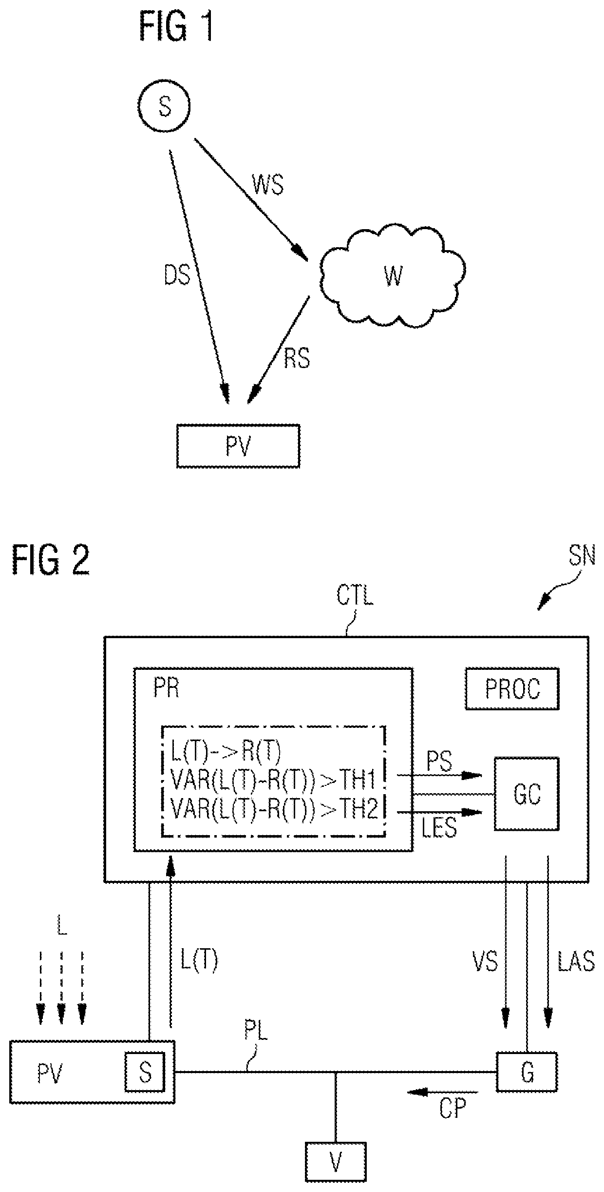
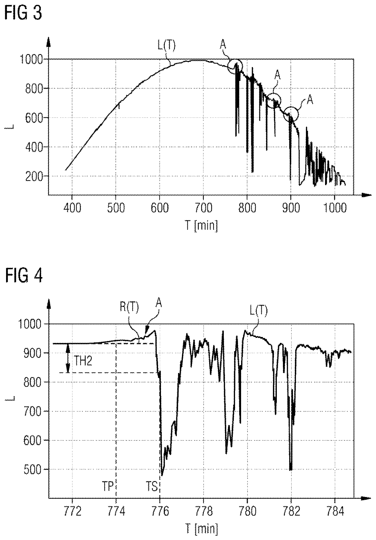
[0025]In order to illustrate an important operating principle of embodiments of the invention, FIG. 1 shows a schematic illustration of a photovoltaic system PV on which the sun S is shining. Direct solar radiation DS hits the photovoltaic system PV along a line of connection between the sun S and the photovoltaic system PV. As soon as a cloud W moves into the vicinity of this line of connection, a portion of the solar radiation WS which hits the cloud W is reflected from the cloud W and additionally hits the photovoltaic system PV as reflected solar radiation RS. The reflected solar radiation RS adds to the direct solar radiation DS, so that the total light irradiation of the photovoltaic system PV briefly increases as the cloud W approaches the line of connection. This increase in the light irradiation can be taken as a sign of imminent shading and therefore of an imminent drop in power of the photovoltaic system PV. In general, the increase can be detected as early as several min...


PUM


Abstract

To control a power network having a photovoltaic system, a time curve of a light radiation of the photovoltaic system is determined, wherein an increase of the time curve in relation to a reference curve of the light radiation is detected. As a result of the detection of the increase, a preparatory measure is then introduced to prepare the power network for an upcoming power drop of the photovoltaic system.

Description

CROSS-REFERENCE TO RELATED APPLICATIONS[0001]This application claims priority to PCT Application No. PCT / EP2016 / 069227, having a filing date of Aug. 12, 2016 based off of German application No. 102015222210.1 having a filing date of Nov. 11, 2015, the entire contents of both of which are hereby incorporated by reference.FIELD OF TECHNOLOGY[0002]Photovoltaic systems are becoming increasingly important as renewable energy sources. However, it goes without saying that a photovoltaic system delivers power only during the day. Furthermore, the output power experiences a considerable drop when clouds move between the sun and the photovoltaic system. In order to nevertheless maintain the supply network voltage in the event of a drop in power of this kind, a further energy source is often provided in the power supply network of a photovoltaic system in order to compensate for the drop in power. Depending on the size of the photovoltaic system, a cloud-related drop in power of this kind take...

Claims


Application Information

Patent Timeline
IPC IPC(8): H02J3/00G01W1/12G01W1/10H02S10/10H02S10/20H02J3/38
CPCH02J3/004H02J3/381G01W1/10H02S10/10H02S10/20H02J2300/26G01W1/12H02J2203/20H02S10/00H02J2300/10H02J2300/24Y02E10/56Y02E60/00Y04S40/20Y04S10/50Y02E70/30
Inventor BAMBERGER, JOACHIMMAYER, PETERSZABO, ANDREI
Owner SIEMENS AG
Why Eureka
Try Eureka