
Hybrid ventilation system

a ventilation system and hybrid technology, applied in ventilation systems, lighting and heating apparatus, heating types, etc., can solve the problems of high electrical power consumption of ventilation systems, increased heating within the house, and saving the cost and energy consumption of cooling systems, so as to achieve the effect of reducing electrical power consumption and large volume of air

Active Publication Date: 2020-08-13
AIRMASTER
View PDF0 Cites 2 Cited by
  • Summary
  • Abstract
  • Description
  • Claims
  • Application Information

AI Technical Summary

Benefits of technology

The present invention relates to a ventilation system that is placed directly in a room to be ventilated, which is a so-called decentralized ventilation system. This system has several technical benefits. Firstly, it reduces the energy consumption because the air is transported from the room to the external environment through a short distance, preferably less than 10 meters. Secondly, this system allows for separate control of ventilation in each room, which is more convenient for some users. Overall, this invention can make older ventilation systems more energy efficient without the need for complete replacement.

Problems solved by technology

The incoming outside air is then further heated by the outgoing inside air in the heat exchanger, causing further heating within the house.
In many buildings in temperate climates, it is possible to avoid active cooling in this way, thus saving the cost and energy consumption of a cooling system.
However, the electrical power consumption of ventilation systems can be very high.

Method used


Image

  • Hybrid ventilation system
  • Hybrid ventilation system
  • Hybrid ventilation system

Examples


Embodiment Construction

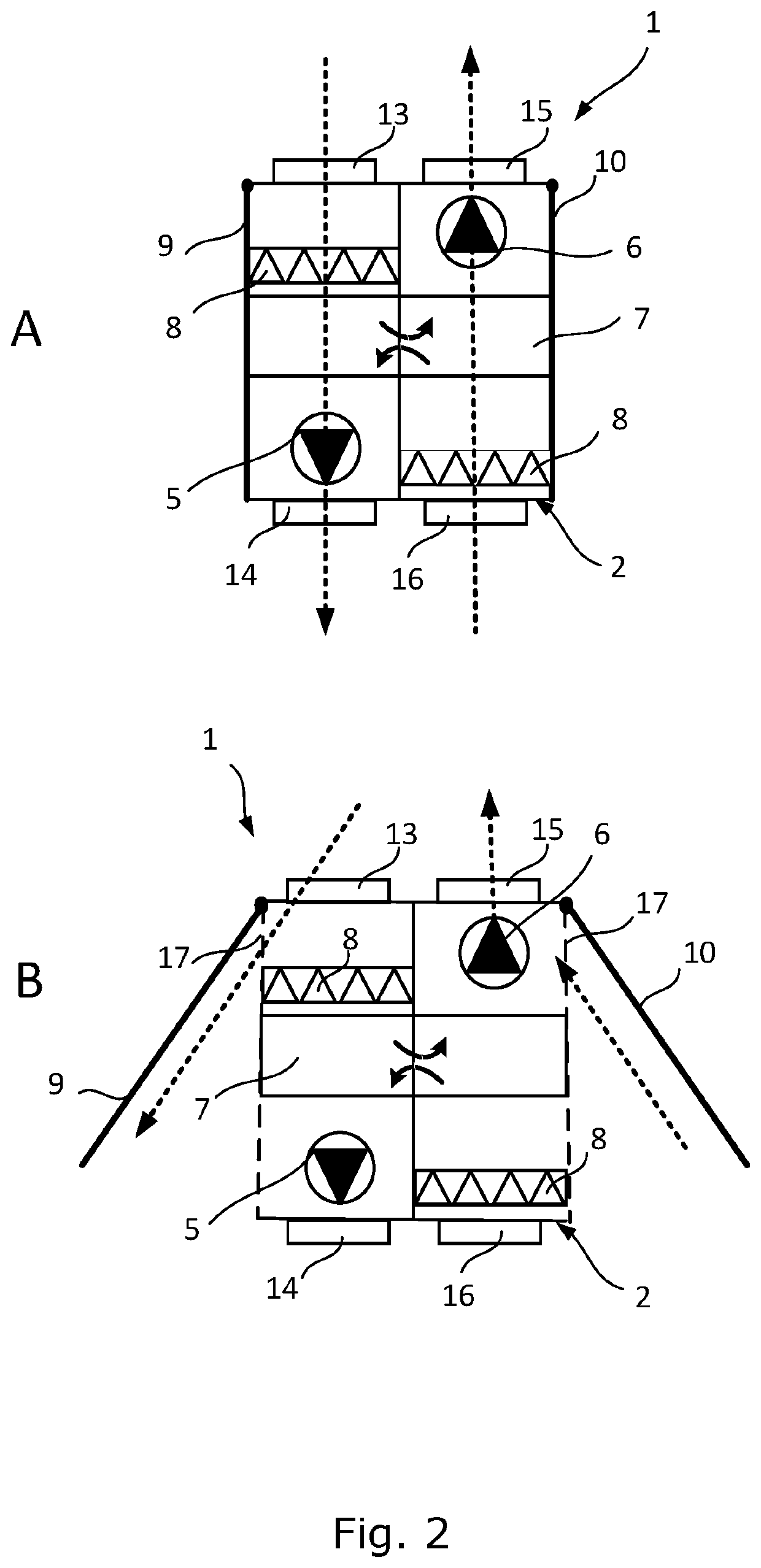
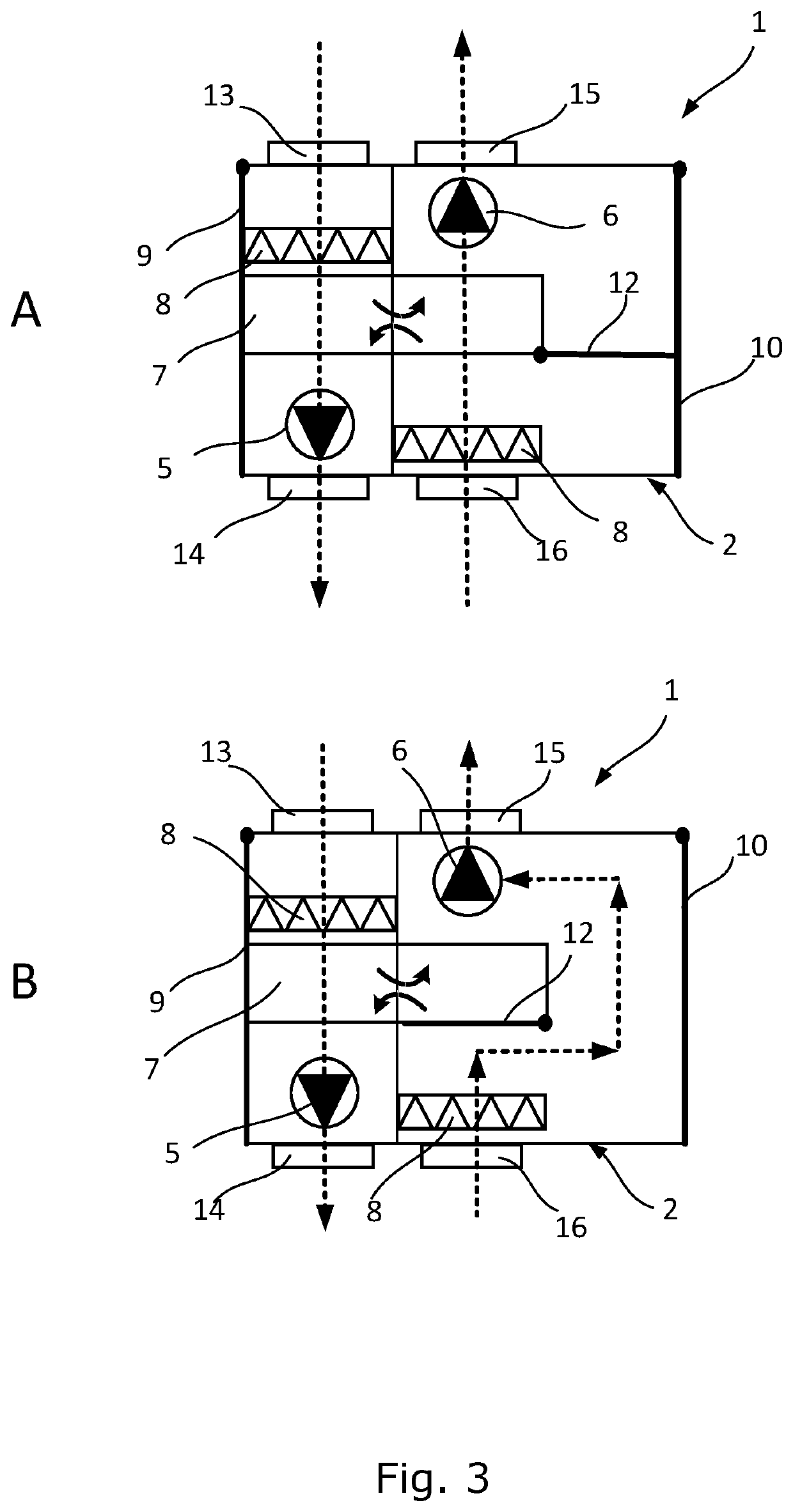
[0096]Reference is made to FIG. 2-5 schematically illustrating different embodiments of a ventilation system according to the present invention. The ventilation system according to the present invention can be operated in at least three modes of operation.

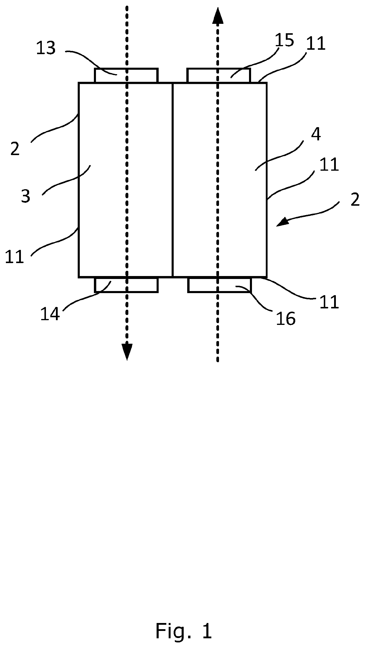
[0097]Reference is made to FIG. 1 illustrating a schematic diagram of an embodiment of a housing of a ventilation system according to the present invention. The housing 2 comprises an inlet channel 3 configured for inletting air into a room, as well as an outlet channel 4 configured for outletting air from a room. The housing 2 further comprises a first inlet 13 in an outer wall 11 of the housing 2, for inletting air into the inlet channel 3 and a first outlet 14 in an outer wall 11 of the housing 2 for outletting air from the inlet channel 3, as well as a second inlet 15 for inletting air into the outlet channel 4 and a second outlet 15 for outletting air from the outlet channel 3.

[0098]Reference is made to FIG. 2, illustrating a ...


PUM


Abstract

The present invention relates to a decentralized hybrid ventilation. The ventilation system comprises a housing having an inlet channel and an outlet channel. A first fan is arranged in the inlet channel for providing an airflow into the room and a second fan is arranged in the outlet channel for providing an airflow out of the room. A heat exchanger and filters are arranged in said channels for exchanging heat between and for filtrating air flowing into the room and air flowing out of the room. Furthermore, the ventilation system comprises a first and a second service door each providing, when open, an opening between the room and one of said channels to diverge the airflow from primarily flowing through the air filters and / or heat exchanger. The ventilation system also comprises a control system configured for switching between different modes of operations.

Description

FIELD OF THE INVENTION[0001]The present invention relates to a hybrid ventilation system, more particularly to a decentralized balanced ventilation system configured to be operated in different modes of operation.BACKGROUND OF THE INVENTION[0002]Recent years' increase in energy prices and concern as to global heating has resulted in a focus on using energy in an efficient manner. Conventionally, heating or cooling of houses or other buildings involves a heat source or a heat sink which raises or reduces the temperature of the air in the building. Furthermore, the air inside the building must be renewed to maintain an acceptable air quality in the building, which can be achieved by balanced ventilation systems.[0003]Balanced ventilation systems extract air from buildings and exhaust it to the outside, but also draws replacement air into the building, thus maintaining the air pressure within the building. Such systems therefore have one flow path for air coming into the building and a...

Claims


Application Information

Patent Timeline
IPC IPC(8): F24F11/00F24F3/16F24F7/007F24F12/00F24F8/10
CPCF24F3/1603F24F7/007F24F12/001F24F11/0001F24F11/65F24F11/77F24F11/81F24F13/14F24F13/20F24F13/28F24F2012/007F24F2013/207Y02B30/56Y02B30/70F24F8/10
Inventor BJØRN, ERIK
Owner AIRMASTER
Learn More