

Phased array antenna
a phased array and antenna technology, applied in the direction of antennas, fibre transmission, electromagnetic transmission non-optical aspects, etc., can solve the problems of difficult to impart a highly accurate time delay to a radio frequency signal, and the phased array antenna shown in fig. 11 is not suitable for use in a millimeter wave band, so as to achieve a lower cost
- Summary
- Abstract
- Description
- Claims
- Application Information
AI Technical Summary
Benefits of technology
Problems solved by technology
Method used
Image

Examples
embodiment 1
[0043](Configuration of Phased Array Antenna)
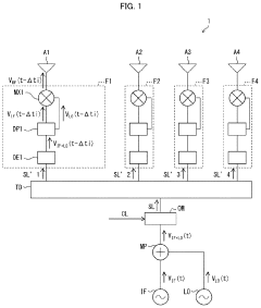
[0044]The following description will discuss, with reference to FIG. 1, a phased array antenna 1 in accordance with Embodiment 1 of the present invention. FIG. 1 is a block diagram illustrating a configuration of the phased array antenna 1.
[0045]As illustrated in FIG. 1, the phased array antenna 1 is a transmitting antenna which includes: a multiplexer MP; an optical modulator OM; a time delay device TD; a feeding circuit group constituted by n feeding circuits F1, F2, . . . and Fn; and an antenna element group constituted by n antenna elements A1, A2, . . . and An. Note here that n represents any integer not less than 2; FIG. 1 illustrates a configuration where n=4.
[0046]The multiplexer MP adds an intermediate frequency signal VIF(t) and a local signal VLO(t) so as to generate a sum signal VIF+LO(t) which equals VIF(t)+VLO(t). In a case where the intermediate frequency signal VIF(t) and the local signal VLO(t) are expressed as shown in F...
embodiment 21
[0103](Configuration of Phased Array Antenna)
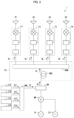
[0104]The following description will discuss, with reference to FIG. 5, a phased array antenna 2 in accordance with Embodiment 2 of the present invention. FIG. 5 is a block diagram illustrating a configuration of the phased array antenna 2.
[0105]As illustrated in FIG. 1, the phased array antenna 2 is a transmitting antenna which includes: an optical modulator OM; a time delay device TD; a feeding circuit group constituted by n feeding circuits F1, F2, . . . and Fn; and an antenna element group constituted by n antenna elements A1, A2, . . . and An. Note here that n represents any integer not less than 2; FIG. 1 illustrates a configuration where n=4.
[0106]The optical modulator OM generates a signal light beam SL by carrying out quadrature amplitude modulation on a carrier light beam CL by use of an intermediate frequency signal VIF(t) and a local signal VLO(t). The intermediate frequency signal VIF(t) and the local signal VLO(t) are, for e...
specific example 1
of Phased Array Antenna
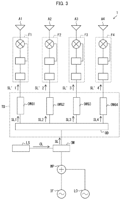
[0115]The following description will discuss, with reference to FIG. 6, Specific Example 1 of the phased array antenna 2. FIG. 6 is a block diagram illustrating a configuration of the phased array antenna 1 in accordance with Specific Example 1.
[0116]The phased array antenna 2 in accordance with Specific Example 1 includes, as components for generating the carrier light beam CL, (i) a light source group constituted by n light sources LS1, LS2, . . . and LSn, and (ii) an optical multiplexer OMP.
[0117]Each light source LSi (i=1, 2, . . . n) generates a carrier light beam CLi. Carrier light beams CL1, CL2, . . . and Cn generated by respective ones of the light sources LS1 through LSn have respective wavelengths λ1, λ2, . . . and λn which differ from each other. The carrier light beam CLi generated by each light source LSi is supplied to the optical multiplexer OMP. Note that in Specific Example 1, a semiconductor laser element is used as each light source LSi.
[01...
PUM
 Abstract
Description
Claims
Application Information