Enclosure Component Perimeter Structures

a technology of enclosure components and perimeter structures, applied in the field of enclosure components, can solve the problems of not being able to adapt the general shape and layout of the house cannot be changed or adapted to the customer's preference, and the size of modular housing often exceeds the normal legal limit, so as to facilitate the provision of enclosure components and reduce on-site set-up costs , the effect of rapid field-level deploymen

Active Publication Date: 2020-08-20
BOXABL INC
View PDF0 Cites 19 Cited by
  • Summary
  • Abstract
  • Description
  • Claims
  • Application Information

AI Technical Summary

Benefits of technology

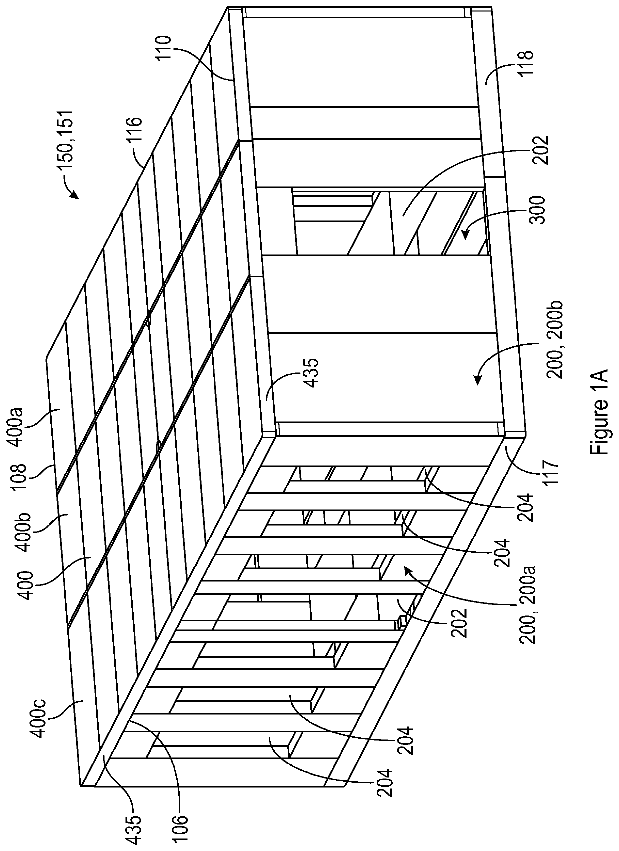
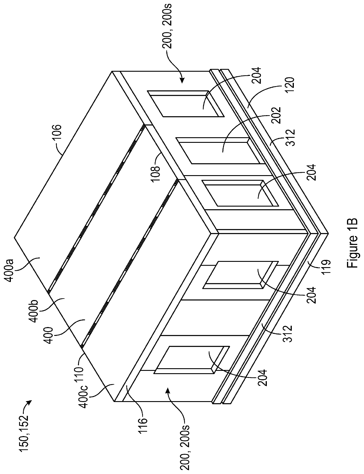
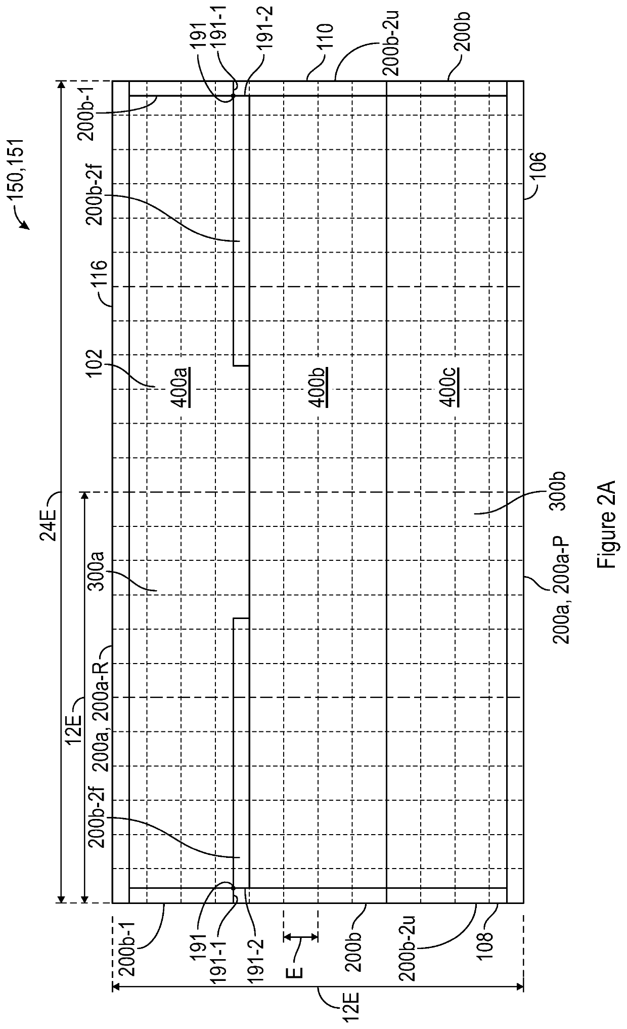
[0007]The present inventions are directed to enclosure component perimeter structures, including hinged structures that can be left in place after delivery, thereby reducing on-site set-up costs. In addition, the hinged and other enclosure component perimeter structures described herein can serve as structural load-bearing members, and also contribute to weather-proofing of the enclosure components to which they are affixed. The present inventions facilitate the provision of enclosure components and enclosure component portions which can be compactly packaged for easy shipment from a factory to a construction site, and which are joined to each other in a manner to permit rapid field-level deployment with factory-level tolerances and repeatability.

Problems solved by technology

A drawback of modular housing is that the prospective buyer can customize the structure layout only to a relatively limited degree.
That is, while certain features, for example a closet, may be added or subtracted from a room, the general shape and layout of the house cannot be changed or adapted to the customer's preference.
Additionally, modular housing often exceeds in size normally-permitted legal limits for road transport.
Thus, in many cases transporting a modular house from factory to site requires oversize load permits, which may impose restrictions on when transport can be undertaken and what routes can be utilized.
All of these requirements and restrictions inevitably increase the cost of the modular housing.

Method used


Image

  • Enclosure Component Perimeter Structures
  • Enclosure Component Perimeter Structures
  • Enclosure Component Perimeter Structures

Examples


first and second embodiments

[0030]Interior Sheathing Layer (282). In the first and second embodiments of the laminate multi-layer design, shown in FIGS. 4A and 4B respectively, the surface of enclosure component 155 that will face toward the interior of structure 150 is optionally provided with an interior sheathing layer 282. It is preferred that interior sheathing layer 282 be fabricated of relatively thick paper, of a weight comparable to that used as the exterior surface of drywall (marketed for example under the trademark Sheetrock®). Interior sheathing layer 282 preferably is unrolled from a continuous roll of paper (the paper roll optionally having a width approximating the width of enclosure component 155) to yield a seamless interior finish for enclosure component 155.

[0031]First Structural Layer (210). A first structural layer 210 is provided in the first embodiment depicted in FIG. 4A and in the second embodiment depicted in FIG. 4B. If used, the interior sheathing layer 282 is bonded to this first ...

third and fourth embodiments

[0047]A third embodiment of the laminate multi-layer design is shown in FIG. 4C. As compared to the second embodiment shown in FIG. 4B, the third embodiment of FIG. 4C has a sheet metal layer 205 in lieu of second structural layer 215, but is otherwise identical in design to the second embodiment shown in FIG. 4B. Sheet metal layer 205, which can be steel or aluminum for example, is made from a plurality of generally planar rectangular metal sheets 206 positioned adjacent to each other to generally cover the full area of the intended enclosure component 155, and joined to each other, such as by riveting or welding. Following joining, the joined metal sheets 206 of sheet metal layer 205 are fastened with a suitable adhesive spread to the second opposing face of foam panels 214 (the face of foam panels 214 distal from structural layer 210).

[0048]It is preferred that the seams between adjacent foam panels 214 not overlay or coincide with the seams in the joined metal sheets 206 of shee...


PUM

PropertyMeasurementUnit
distanceaaaaaaaaaa
perimeteraaaaaaaaaa
angleaaaaaaaaaa

Abstract

An enclosure member for a building structure comprising a planar laminate having a first facing layer; a layer of foam having a first face and a second opposing face; and a second facing layer; where the first facing layer is fastened to the first face of the layer of foam, and the second facing layer is fastened to the second opposing face of the layer of foam. An edge of the enclosure is provided with a perimeter structure that can perform one or more of a sealing function, an edge reinforcement function and a pivotable joining function with another enclosure, in accordance with the particular embodiment.

Description

CROSS-REFERENCES TO RELATED APPLICATIONS[0001]This application claims the benefit of U.S. Provisional Application No. 62 / 805,710, filed Feb. 14, 2019 and U.S. Provisional Application No. 62 / 960,991, filed Jan. 14, 2020.BACKGROUND OF THE INVENTIONField of the Invention[0002]The inventions herein relate to structures, such as dwellings and other buildings for residential occupancy, commercial occupancy and / or material storage, and to components for such structures.Description of the Related Art[0003]In the field of residential housing, the traditional technique for building homes is referred to as “stick-built” construction, where a builder constructs housing at the intended location using in substantial part raw materials such as wooden boards, plywood panels, and steel Lally columns. The materials are assembled piece by piece over a previously prepared portion of ground, for example, a poured concrete slab or a poured concrete or cinder block foundation.[0004]There have been a varie...

Claims


Application Information

Patent Timeline
Patent Type & Authority Applications(United States)
IPC IPC(8): E04B1/344E04C2/284B32B5/18B32B5/32B32B5/02B32B15/04
CPCB32B2262/101E04B1/344E04B2001/34389B32B5/32B32B15/046E04C2/284B32B5/024B32B2419/00B32B5/18E04B1/343E04B1/34315E04B1/34321E04C2/288E04B1/34853B32B7/12B32B3/08B32B2307/54B32B19/046B32B2307/3065B32B2307/304B32B2607/00B32B2307/732B32B3/04B32B7/08B32B19/047B32B15/14B32B2307/7244B32B19/041B32B5/028B32B15/18B32B19/06B32B5/245B32B21/047B32B2266/0228B32B3/18B32B3/266B32B3/20B32B15/20B32B2307/712B32B2307/546B32B3/30B32B15/043E04B1/3445E04B1/34384E04B1/34317E04B1/3442B32B5/20
Inventor TIRAMANI, PAOLOTIRAMANI, GALIANODENMAN, KYLE
Owner BOXABL INC
Why Eureka
Try Eureka