Damper device

a technology of damper device and damper, which is applied in the direction of fluid gearing, coupling, and axial length can solve the problems of reducing the vibration affecting the performance of the damper device, and affecting the effect of the rotary inertia mass damper, etc., so as to improve the stiffness improve the damping performance of the damper device, and transmit large torque

Active Publication Date: 2020-08-20
QM POWER +2
View PDF0 Cites 0 Cited by
  • Summary
  • Abstract
  • Description
  • Claims
  • Application Information

AI Technical Summary

Benefits of technology

[0009]In the damper device according to the present disclosure, when torque transmitted between the input element and the output element is greater than or equal to the predetermined value, the plurality of second elastic bodies act in parallel with the plurality of first elastic bodies. This increases the stiffness of the damper device in accordance with an increase in torque transmitted between the input element and the output element, thus making it possible to transmit large torque or to receive impact torque or the like by using the first and second elastic bodies acting in parallel with each other. Further, in the damper device according to the present disclosure, the plurality of second elastic bodies are located at a different position than the plurality of first elastic bodies in the radial direction of the rotating elements and are circumferentially aligned with the plurality of pinion gears. This makes it possible to control an increase in the axial length and outside diameter of the damper device while providing an appropriate circumferential length (stiffness) of the first elastic bodies. Therefore, it is possible to ensure good vibration damping performance of the damper device including the rotary inertia mass damper while controlling an increase in the size of the damper device.

Problems solved by technology

Nevertheless, an increase in the diameter of the elastic body may cause an increase in the axial length and outside diameter of the damper device, and the effect of the rotary inertia mass damper to damp vibrations may deteriorate due to an increase in hysteresis of the elastic body.
In contrast, an increase in the stiffness of the elastic body causes a drop in vibration damping performance of the damper device in a low rotation speed range.

Method used


Image

  • Damper device
  • Damper device
  • Damper device

Examples


Embodiment Construction

[0018]Next, an embodiment of the present disclosure is described with reference to the drawings.

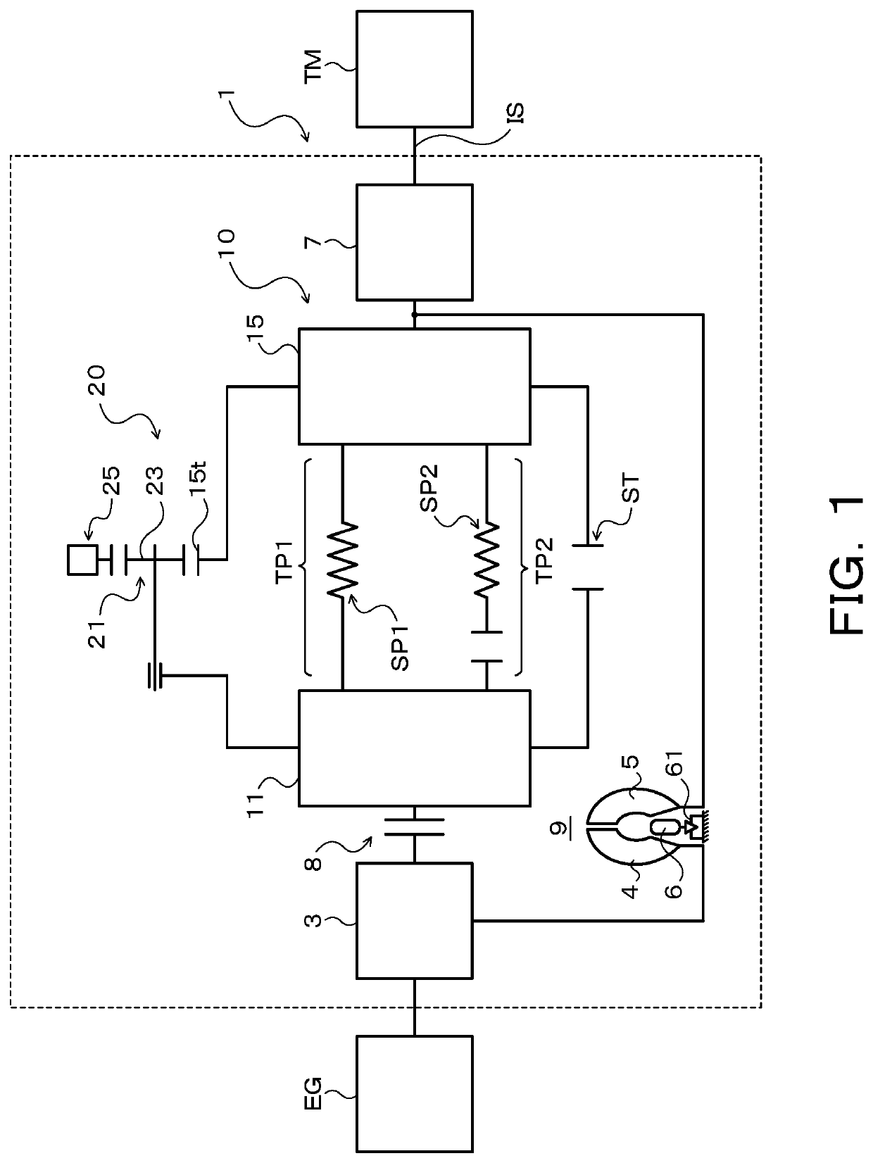
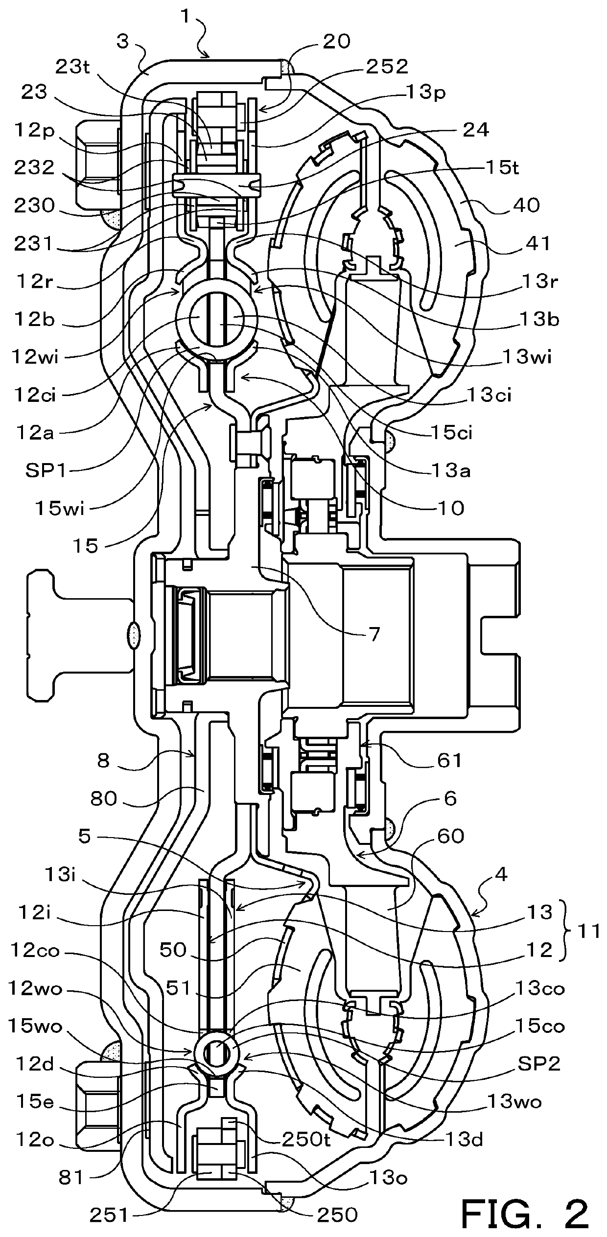
[0019]FIG. 1 is a schematic diagram of a starting apparatus 1 including a damper device 10 according to the present disclosure, and FIG. 2 is a cross-sectional view of the starting apparatus 1. The starting device 1 illustrated in these drawings is adapted to be mounted on a vehicle having an engine (an internal combustion engine) EG as a drive unit. In addition to the damper device 10, the starting device 1 includes the following: a front cover 3 as an input member coupled to a crankshaft of the engine EG to receive torque transmitted from the engine EG; a pump impeller (an input-side fluid transmission element) 4 fixed to the front cover 3; a turbine runner (an output-side fluid transmission element) 5 rotatable coaxially with the pump impeller 4; a damper hub 7 as an output member coupled to the damper device 10 and fixed to an input shaft IS of a transmission TM that is an automatic t...


PUM


Abstract

A damper device includes rotating elements including an input element and an output element, first elastic bodies that each transmit torque between the input element and the output element, a plurality of second elastic bodies that act in parallel with the plurality of first elastic bodies when torque transmitted between the input element and the output element is greater than or equal to a predetermined value, and a rotary inertia mass damper. The rotary inertia mass damper includes a sun gear, a carrier that rotatably supports a plurality of pinion gears, and a ring gear that meshes with the plurality of pinion gears and that serves as a mass body. The plurality of second elastic bodies are located at a different position than the plurality of first elastic bodies in a radial direction of the rotating elements and are circumferentially aligned with the plurality of pinion gears.

Description

CROSS REFERENCE TO RELATED APPLICATIONS[0001]This application is a National Stage of International Application No. PCT / JP2018 / 042086, filed Nov. 14, 2018, claiming priority to Japanese Patent Application No. 2017-219520, filed Nov. 14, 2017, the contents of which are incorporated in their entirety.TECHNICAL FIELD[0002]The present disclosure relates to a damper device including an elastic body that transmits torque between an input element and an output element, and a rotary inertia mass damper.BACKGROUND ART[0003]One conventionally known damper device of this type includes the following: an elastic body that is elastically deformed by relative rotation between an input element (a drive plate) and an output element (a driven plate); and a rotary inertia mass damper that includes a planetary gear mechanism having a sun gear, a ring gear that rotates as a unit with the input element, and a carrier that supports multiple pinion gears and that rotates as a unit with the output element (r...

Claims


Application Information

Patent Timeline
Patent Type & Authority Applications(United States)
IPC IPC(8): F16F15/134F16H45/02F16D3/12F16F15/14
CPCF16F15/1478F16H2045/0268F16D3/12F16H2045/0226F16H45/02F16F15/13469F16H1/28F16F15/13484F16H2045/0263
Inventor YOSHIKAWA, TAKUYAKINOSHITA, TOMONORITANIGUCHI, TETSUROKATO, AKIYOSHIOI, YOICHI
Owner QM POWER
Why Eureka
Try Eureka