Fuel injector

a fuel injector and fuel injection technology, applied in the field of fuel injectors, can solve the problems of reducing the fatigue reducing the strength of the valve seat body, and bending of the cup area, so as to achieve simple and cost-effective manufacturing capability, reduce the effect of strength-relevant tensions and increase load capacity

Inactive Publication Date: 2020-08-27
ROBERT BOSCH GMBH
View PDF54 Cites 0 Cited by
  • Summary
  • Abstract
  • Description
  • Claims
  • Application Information

AI Technical Summary

Benefits of technology

[0008]A further advantage of the present invention is that fewer soot deposits arise on the outer side of the cone-like middle area during engine operation than in the case of known fuel injectors. A temperature distribution which prevents the rapid growth of the soot coatings is achieved in the component due to the design according to the present invention of the valve seat body.
[0009]Because of the low coating formation on the surface of the valve seat body, the design according to the present invention offers greater security against the clogging of the injection openings (“carbonization”). In consideration of the fuel quality, which varies greatly worldwide, this robust behavior is very advantageous.
[0010]Furthermore, it is advantageous that the resulting increase of the particle emissions in the exhaust gas induced by continuous engine operation is less than in the case of fuel injectors according to the related art (reduction of the PN drift).
[0011]Since the wavy cone according to the present invention has an improved cooling effect and a lesser tendency toward coating formation, fewer particle emissions are also formed after continuous operation.
[0012]Advantageous refinements of and improvements on the fuel injector specified in claim 1 are possible by way of the measures set forth in the subclaims.
[0013]It is particularly advantageous that the geometrical design of the valve seat body is adaptable on its lower end face facing toward the combustion chamber very flexibly to desired installation conditions and requirements for the engine operation.

Problems solved by technology

These loads act, with the risk of bending of the cup area, with negative influence on the quality of the valve seat surface, the leak tightness requirements, and the fatigue strength of the valve seat body in this area.

Method used


Image

  • Fuel injector
  • Fuel injector
  • Fuel injector

Examples


Embodiment Construction

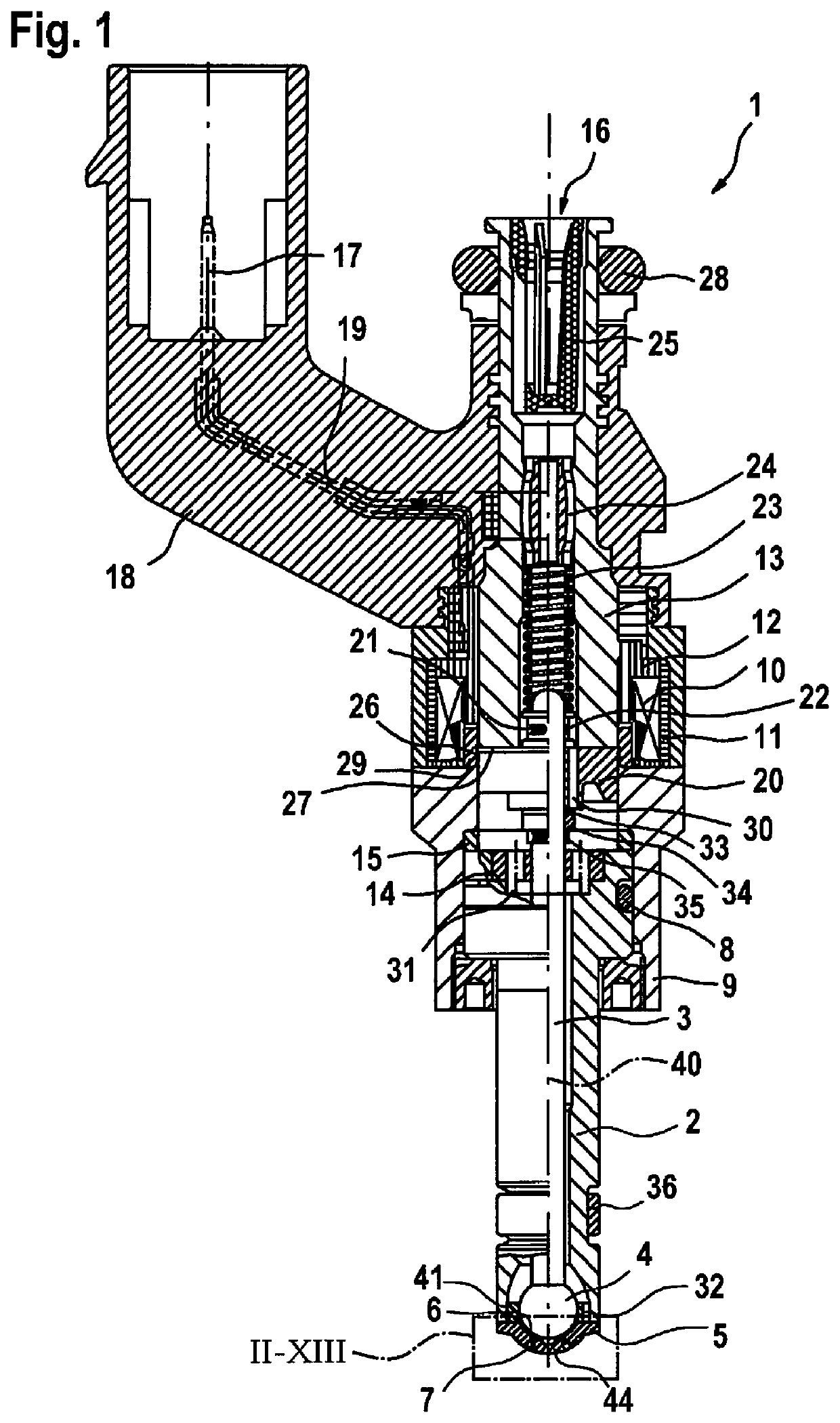
[0028]A known example of a fuel injector 1 shown in FIG. 1 is designed in the form of a fuel injector 1 for fuel injection systems of mixture-compressing, spark-ignited internal combustion engines. Fuel injector 1 is suitable in particular for the direct injection of fuel into a combustion chamber (not shown) of an internal combustion engine.

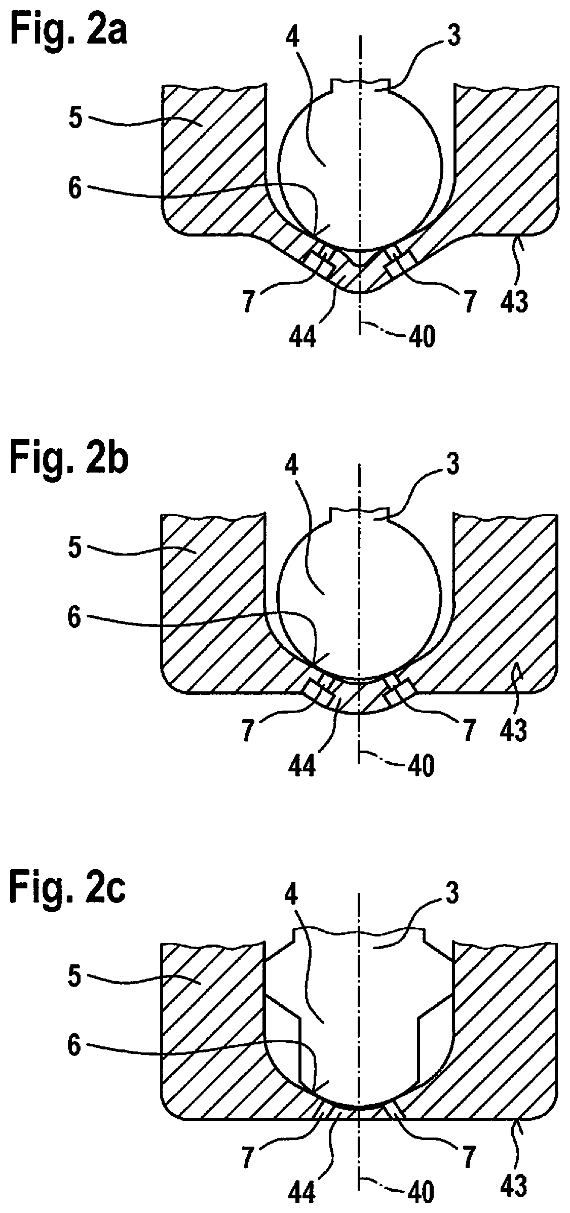
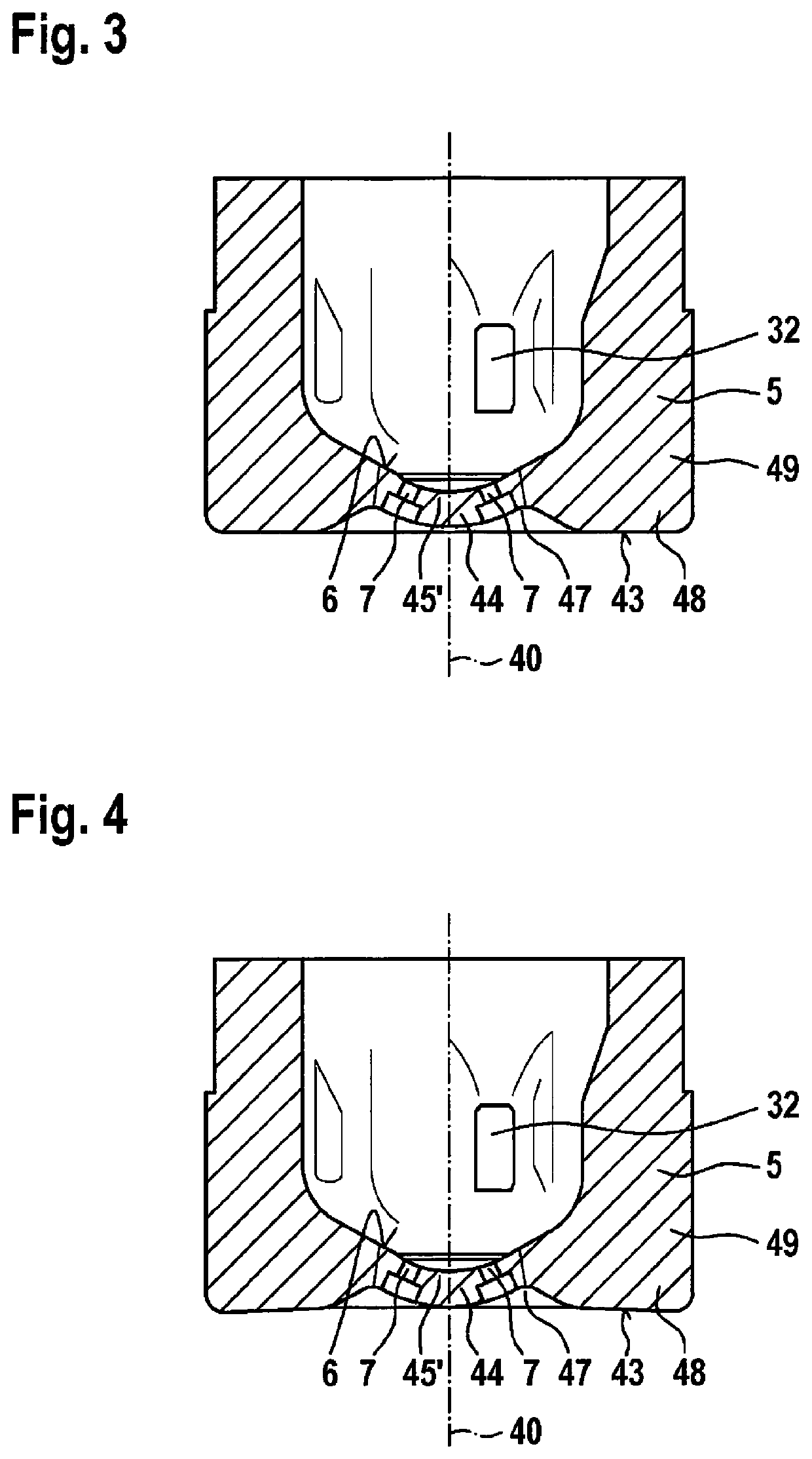
[0029]Fuel injector 1 includes a nozzle body 2, in which a valve needle 3 is situated. Valve needle 3 is operationally connected to a valve closing body 4, which cooperates with a valve seat surface 6 situated on a valve seat body 5 to form a seal seat.

[0030]Valve seat body 5 and nozzle body 2 may also be designed in one piece. Fuel injector 1 is, in the exemplary embodiment, an inwardly opening fuel injector 1, which has at least one injection opening 7, but typically at least two injection openings 7. Fuel injector 1 is ideally, however, designed as a multi-hole injector and therefore has between four and thirty injection openings 7. Nozzle bo...


PUM


Abstract

The fuel injector according to the invention is distinguished in that a particularly high structural strength and vibration resistance of the valve seat body (5) is provided. The fuel injector (1) includes an excitable actuator for actuating a valve closing body, which forms a seal seat together with a valve seat surface (6) formed on a valve seat body (5), and injection openings (7), which are formed downstream of the valve seat surface (6), the injection openings (7) being introduced into a middle area (44) of the valve seat body (5) protruding outwardly like a cone in the injection direction. The cone-like axially protruding middle area (44) of the valve seat body (5) ends radially outside the orifice areas of all injection openings (7) in a recessed depression (47), from which, in turn, an axially protruding border area (48) of the valve seat body (5) adjoins radially outwardly, so that an overall wavy cone contour of the valve seat body (5) is formed in cross section. The fuel injector is particularly suitable for direct injection of fuel into a combustion chamber of a mixture-compressing spark-ignited internal combustion engine.

Description

BACKGROUND INFORMATION[0001]The present invention is directed to a fuel injector according to the definition of the species in the main claim.[0002]Specific embodiments of known valve seat bodies are shown in FIGS. 1, 2a, 2b, and 2c. FIGS. 2a, 2b, and 2c show schematic views of three fundamentally typical constructions of valve seat bodies having injection openings. While in the known and proven approach according to FIG. 2c, the valve seat body terminates the downstream valve end of the fuel injector toward the combustion chamber with a planar and flat end face, in the also known approaches according to FIGS. 2a and 2b, the valve seat bodies are formed having a middle area of the valve seat body which includes the injection openings and protrudes outward like a cone in the injection direction. This is either a disk cone having a conical lateral surface in the middle area (for example, DE 10 2013 219 027 A1) or a sphere cone having a bulge extending spherically convexly outwardly (f...

Claims


Application Information

Patent Timeline
Patent Type & Authority Applications(United States)
IPC IPC(8): F02M51/06F02M61/18
CPCF02M2200/9053F02M51/061F02M61/1806F02M2200/8046F02M2200/9007F02M2200/03F02M2200/06
Inventor POHLMANN, JENSGARTUNG, KAI
Owner ROBERT BOSCH GMBH
Why Eureka
Try Eureka