
Interposer Assembly and Method

a technology of interposer and assembly, which is applied in the direction of fixed connections, semiconductor/solid-state device details, coupling device connections, etc., can solve the problems of affecting the formation of electrical connections between the contact surface and the pad, and achieve the effect of reducing the compression load on the assembly, high spring rate, and reducing the spring ra

Active Publication Date: 2020-08-27
AMPHENOL INTERCON SYST
View PDF0 Cites 1 Cited by
  • Summary
  • Abstract
  • Description
  • Claims
  • Application Information

AI Technical Summary

Benefits of technology

The interposer assembly described in this patent has contacts with redundant arms and small contact areas that increase the contact pressure, ensuring reliable electrical connections. The contact points are located at the inner part of each arm to improve the formation of the electrical connection. The contacts are compressible and can be compressed into the passages in the plate to form electrical connections with the contact pads on the substrate without deforming the substrate or compressing the contacts to an unreasonable degree. This reduces the load on the assembly and the need for strong clamps to retain the compressed assemblies together.

Problems solved by technology

Impurities, oxides or contaminants on either the contact surface or the pad can impair formation of the electrical connection between the contact surface and the pad.

Method used


Image

  • Interposer Assembly and Method
  • Interposer Assembly and Method
  • Interposer Assembly and Method

Examples


Embodiment Construction

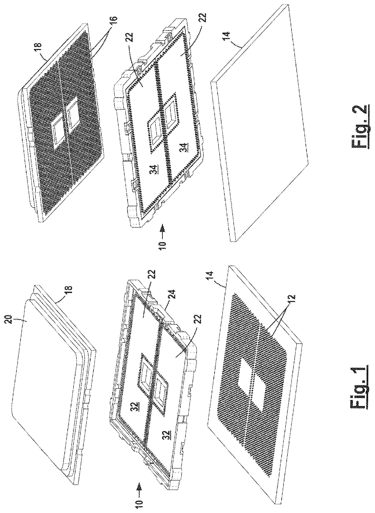
[0043]Interposer assembly 10 forms electrical connections between a large number of contact pads 12 on lower substrate 14 and a correspondingly large number of contact pads 16 on upper substrate 18. The pads 12 and 16 are arranged in rows and columns in land grid arrays. An integrated circuit 20 may be mounted on the upper surface of substrate 18 with electrical connections to pads 16. Substrate 18 is removably mounted on assembly 10. Assembly 10 may be permanently mounted on substrate 14.

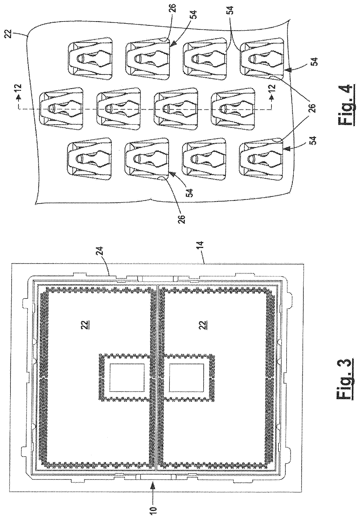
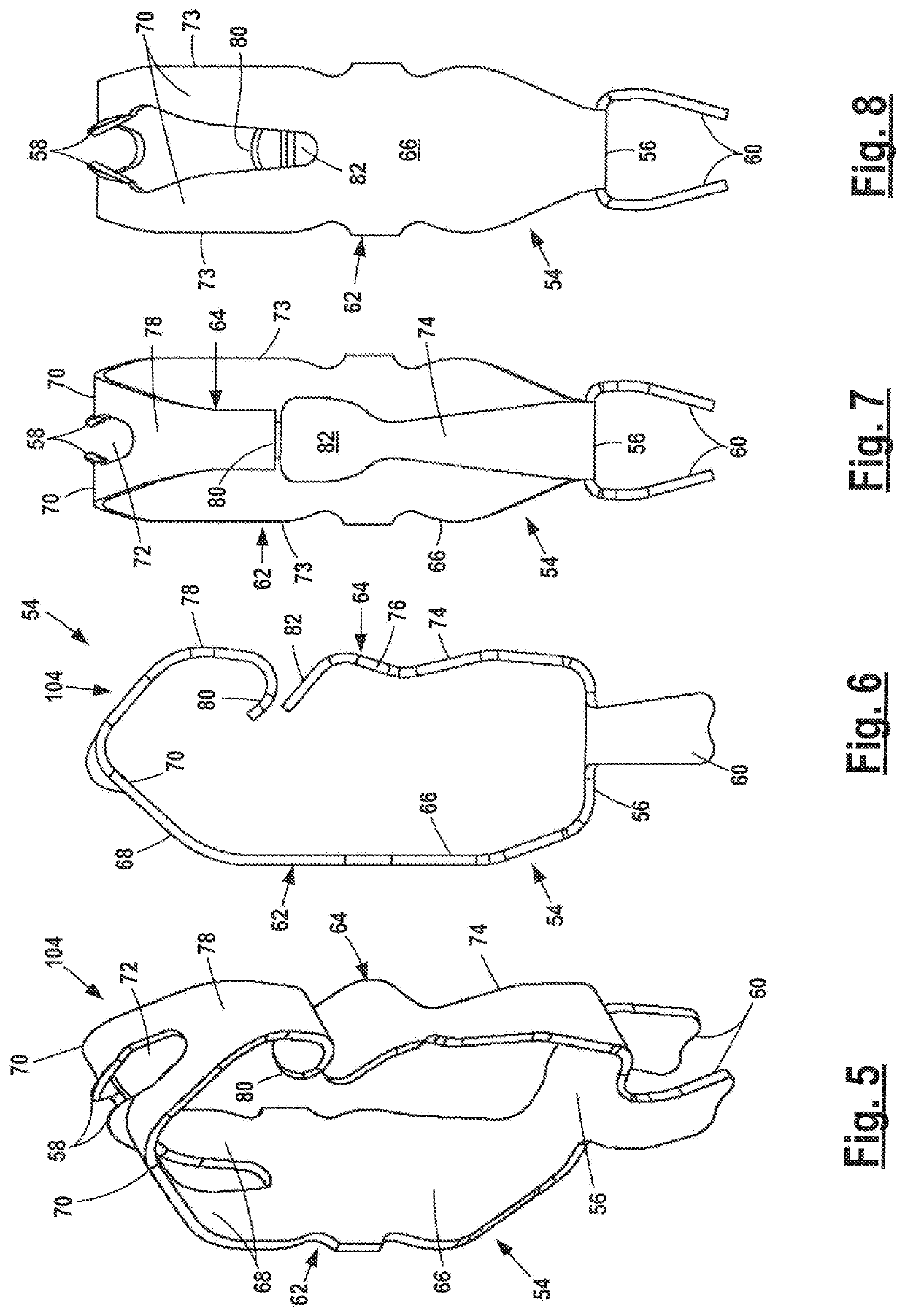
[0044]Interposer assembly 10 includes two rectangular molded insulating, plastic interposer plates 22 fitted in surrounding frame 24. Each plate 22 has a large number of closely spaced contact passages 26 arranged in a closely spaced land grid array. A two-conductor contact 54 is positioned in each contact passage 26 to form a reliable dual current path electrical connection between opposed contact pads 12 and 16 on substrates 14 and 18. Pads 12 and 16 are located below and above each passage 26. C...


PUM


Abstract

An interposer assembly including a plate and a plurality of conductive contacts extending through plate passages for forming electrical connections with pads on overlying and underlying substrates.

Description

FIELD OF THE DISCLOSURE[0001]The disclosure relates to an interposer assembly including a plate and a plurality of conductive contacts located in plate through-passages. The contacts allow the formation of electrical connections between contact pads on opposed overlying and underlying substrates. The contacts may include one or more cantilever arms to facilitate forming electrical connections with the contact pads.BACKGROUND OF THE DISCLOSURE[0002]Interposer assemblies with molded plastic plates and metal contacts inserted in passages in the plates are used for forming electrical connections between contact pads on opposed substrates. The contacts and pads are spaced very close together in land grid array rows and columns to establish a large number of differential pair signal and ground connections extending through the plate.[0003]Conventional interposer assemblies include contacts having opposed ends which form pressure connections with pads on substrates. Permanent soldered conn...

Claims


Application Information

Patent Timeline
Patent Type & Authority Applications(United States)
IPC IPC(8): H01R13/24H05K1/11H01L23/00
CPCH01L24/14H05K1/11H01R13/2435H01R13/2442H01R13/245H01R12/73H01R12/7082H01R12/57
Inventor TAYLOR, PAUL R.DO, TRENTHILEMAN, JAMES S.
Owner AMPHENOL INTERCON SYST
Learn More