
A dialysis machine

a dialysis machine and dialysis solution technology, applied in the field of dialysis machines, can solve the problems of up to 120 litres of dialysate solution, slight errors or uncertainties in measurement, etc., and achieve the effect of greatly reducing the attenuation of the sensor signal and minimising unwanted reflections

Active Publication Date: 2020-09-03
QUANTA DIALYSIS TECH LTD
View PDF0 Cites 3 Cited by
  • Summary
  • Abstract
  • Description
  • Claims
  • Application Information

AI Technical Summary

Benefits of technology

The patent is about a new design for a hemodialysis machine that can be transported with patients, making treatment more convenient. The machine is small and can be used at home or in a medical facility. The use of disposable components, such as sensor cells and cartridges, ensures cleanliness and reduces the need for cleaning after each session. This design also reduces the risk of contamination and infection.

Problems solved by technology

However, this requires up to 120 litres of dialysate solution for each dialysis session.
Typically, such measurements are taken with respect to an absolute reference point which may result in slight errors or uncertainties in the measurements due to minor differences between the material / solution used to record the absolute reference point and the material / solution used in the dialysis machine.

Method used


Image

  • A dialysis machine
  • A dialysis machine
  • A dialysis machine

Examples


Embodiment Construction

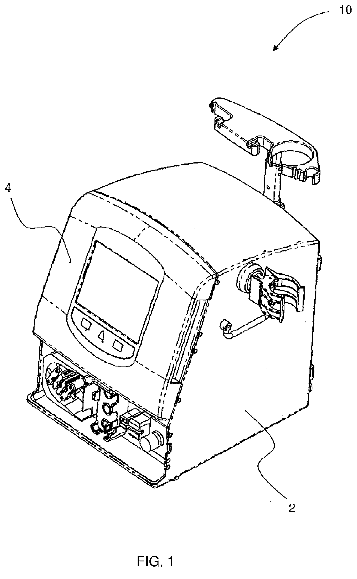
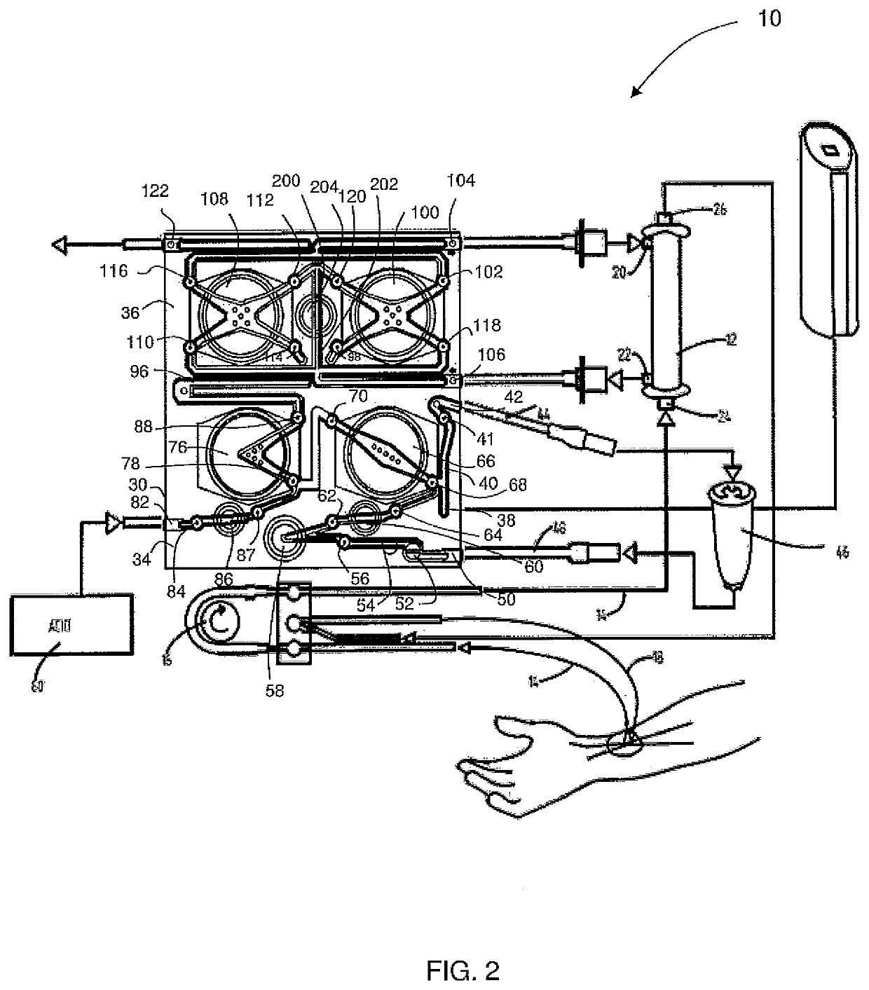
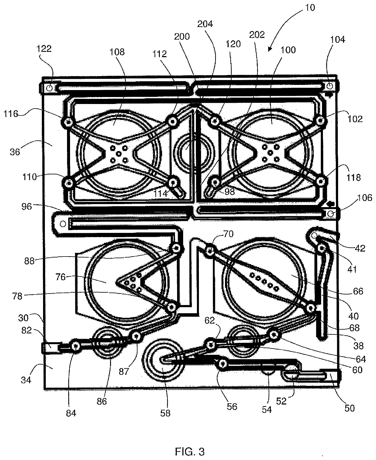
[0051]In FIG. 1, a dialysis apparatus 10 has a body 2 and a hinged door 4. The door 4 is hinged so as to allow a dialysis cartridge 30 (see FIG. 3) to be received between the body 2 and the door 4 before the door is closed to engage the cartridge 30. The body 2 includes a platen provided with pneumatic pumps for operating the cartridge 30 and a series of sensors for sensing a dialysate solution (and constituent components thereof) along a fluid pathway for delivering a dialysate solution, as will be discussed in further detail below. The dialysate solution flows along a pre-dialysis pathway into a dialyser 12 and along a post-dialysis pathway towards a drain outlet 122.

[0052]The cartridge 30 has a platen side 31 and a door side 32. The platen side 31 engages the platen on the main body 2 of the machine 10, and the door side 32 engages the door 4 of the machine 10. The cartridge 30 is formed from an acrylic, such as SG-I0, which is moulded in two parts (the machine side and the patie...


PUM


Abstract

A hemodialysis machine comprising a fluid pathway for delivering a dialysate solution, wherein the fluid pathway comprises a pre-dialysis pathway and a post-dialysis pathway, a dialyser for dialysing patient's blood using the dialysate solution, the dialyser connected between the pre-dialysis pathway and the post-dialysis pathway, a first sensor system configured to sense a characteristic of the dialysate solution at a first location on the pre-dialysis pathway, a second sensor system configured to sense a characteristic of the dialysate solution at a second location on the post-dialysis pathway, and a control system configured to make a comparative analysis of the measurements taken by the first sensor and the second sensor for monitoring the composition of the dialysate solution.

Description

FIELD OF THE INVENTION[0001]The present invention relates to a dialysis machine.BACKGROUND OF THE INVENTION[0002]Dialysis is a treatment which replaces the renal function of removing excess fluid and waste products, such as potassium and urea, from blood. The treatment is either employed when renal function has deteriorated to an extent that uremic syndrome becomes a threat to the body's physiology (acute renal failure) or, when a longstanding renal condition impairs the performance of the kidneys (chronic renal failure).[0003]There are two major types of dialysis, namely hemodialysis and peritoneal dialysis. In peritoneal dialysis treatment, a dialysate solution is run through a tube into the peritoneal cavity. The fluid is left in the cavity for a period of time in order to absorb the waste products, and is subsequently removed through the tube for disposal. It is common for patients in the early stages of treatment for a longstanding renal condition to be treated by peritoneal di...

Claims


Application Information

Patent Timeline
Patent Type & Authority Applications(United States)
IPC IPC(8): A61M1/16
CPCA61M1/1607A61M1/1621A61M2205/12A61M2205/3375A61M1/1609A61M1/14A61M2205/3306A61M1/1605A61M1/155A61M1/1565A61M1/154A61M1/15625A61M1/1561
Inventor MILAD, JOHNBUCKBERRY, CLIVEWALLACE, MARK
Owner QUANTA DIALYSIS TECH LTD
Learn More