Pyrotechnic switching device

a switching device and pyrotechnic technology, applied in the direction of electrical devices, conductor severing switches, switches operated by excess current, etc., can solve the problems of coupling of this type, interruption of current, and tripping of switches, so as to improve the reliability of electrical switching and operation. reliable

Inactive Publication Date: 2020-09-03
MERSEN FRANCE SB +1
View PDF0 Cites 15 Cited by
  • Summary
  • Abstract
  • Description
  • Claims
  • Application Information

AI Technical Summary

Benefits of technology

[0019]One advantage of the second fuse element is that the formation of an electric arc at the broken conductive portion is avoided, because the current can still circulate in the additional fuse element during a short period before the latter is tripped and interrupts the circuit. In addition, as the additional fuse element is subjected during this instant to the entire intensity circulating in the electrical circuit, its operation is reliable. This advantageously allows improving the reliability of the electrical switching performed.

Problems solved by technology

When the current passing through the conducting portion reaches the tripping threshold of the fuse (predetermined current value), all the current then passes through the first initiator, which also causes its tripping and the interruption of the current due to breakage of the conductive portion.
Coupling of this type could then impair the control element in the event of overrunning the threshold value of the current at which the fuse element is tripped.
Secondly, the current circulating in the additional fuse element will melt the latter, which will cause the complete interruption of the electrical current circulating in the circuit.

Method used


Image

  • Pyrotechnic switching device
  • Pyrotechnic switching device
  • Pyrotechnic switching device

Examples


first embodiment

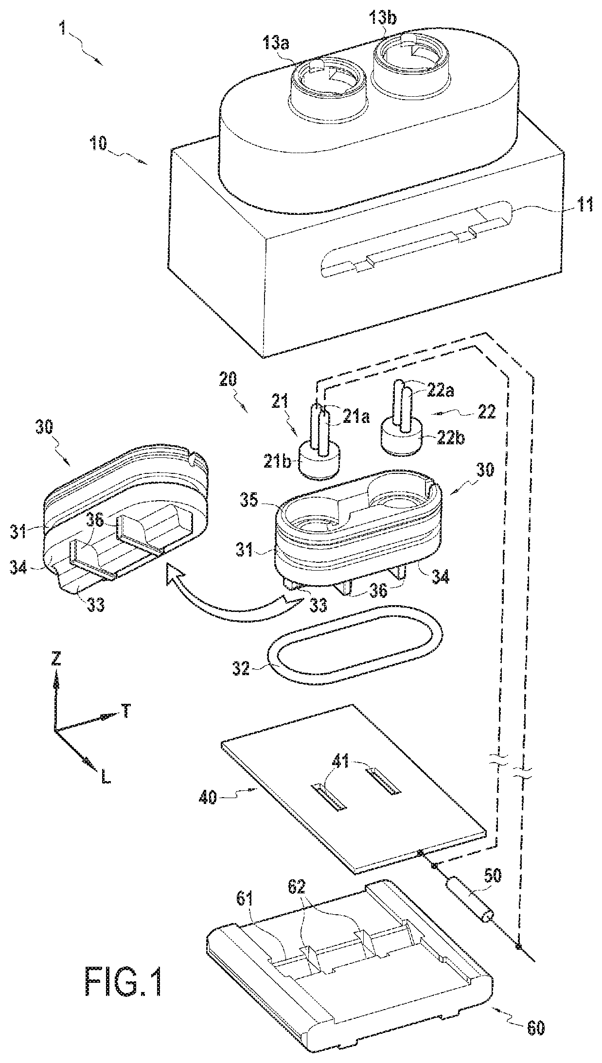
[0036]FIG. 1 shows an exploded view of a switching device 1 according to the invention. The illustrated switching device 1 comprises: a body 10, a pyrotechnic initiation system 20, a piston 30, a conductive portion 40, a fuse element 50, and a support 60. The fuse element 50 is, according to the invention, connected in series with the conductive portion 40. In the example illustrated, the longitudinal direction L corresponds to the direction in which the conductive portion 40 extends in the device 1. The transverse direction T is perpendicular to the direction L in the plane of the conductive portion 40.

[0037]The body 10 comprises two lateral openings 11 on two opposite faces of the body 10 (only one lateral opening 11 is visible in FIG. 1) by which the support 60 can be inserted into the interior of the body 10, a lower opening 12 (FIGS. 2A-3B) by which the piston 30 can be inserted into the interior of the body 10, and two upper openings 13a and 13b protruding on an upper face of ...

second embodiment

[0048]FIGS. 5 and 6 show respectively a switching device 1′ according to the invention in longitudinal section, and the conductive portion 40 that it comprises. The device 1′ differs from the device 1 described previously by the fact that the fuse element 50′ constitutes a thinned zone of the conductive portion 40, as can be seen better in FIG. 6. Electrical wires (shown by dotted lines) can thus be provided in the device 1′ to connect the connectors 21a of the first initiator 21 in parallel with the fuse element 50′, as illustrated in FIG. 5. The switching device 1′ operates in the same manner as the device 1 described previously.

third embodiment

[0049]Finally, FIG. 7 shows a switching device 1″ according to the invention, in longitudinal section. The device 1″ differs from the device 1 described previously by the fact that the fuse element 50 is present inside the body 10 and in a second chamber, consisting here of a cavity formed by the opening 12 and delimited by the support 60, distinct from the chamber 15. As before, electrical wires (shown by dotted lines) can be provided in the device 1″ to connect the connectors 21a of the first initiator 21 in parallel with the fuse element 50, as shown in FIG. 7. The switching device 1″ operates in the same manner as the devices 1 and 1′ described previously.


PUM


Abstract

A pyrotechnic switching device comprising a first and a second pyrotechnic initiators, and a body in which are present: an electrically conductive portion, and a mobile switching element having an insulating relief facing the conductive portion. The device also comprises a fuse element connected in series with the conductive portion, the first initiator being connected to the terminals of the fuse element so that tripping the fuse element actuates the first initiator, each initiator being configured to cause the device to switch from a current conducting configuration to a current interrupting configuration, the mobile switching element being set in motion toward the conductive portion in order to break it by the impact of the relief during switching from the first to the second configuration.

Description

BACKGROUND OF THE INVENTION[0001]The present invention relates to the general field of electrical switching devices, and more particularly to those of the type using pyrotechnic actuation. The invention also relates to an electrical power supply system secured by a device of this type.[0002]Pyrotechnic switching devices are known comprising a body in which is present a pyrotechnic initiator configured, when it is triggered, to set in motion a piston provided with a relief in the direction of a conductive bar, to cut through it. Documents WO 2016 / 038043 and WO 2016 / 038050 show examples of devices of this type which allow accomplishing switching in the event of excess current in a circuit.[0003]It would be desirable to switch the current, not only in the event of excess current, but also when a non-electrical anomaly occurs (a shock for example). There exists therefore a need to dispose of a reliable, compact and low-cost switching solution to accomplish this.Object and Summary of the...

Claims


Application Information

Patent Timeline
Patent Type & Authority Applications(United States)
IPC IPC(8): H01H85/165H02H1/00
CPCH01H85/165H02H1/0007H01H39/006H01H83/20H01H85/0039H01H85/0241H01H2085/466
Inventor MATHIEU, ALEXANDRELORENZON, ROMAINDE PALMA, JEAN-FRANÇOIS
Owner MERSEN FRANCE SB
Why Eureka
Try Eureka