RF device for tissue treatment

Active Publication Date: 2020-09-10
INMODE LTD
View PDF0 Cites 25 Cited by
  • Summary
  • Abstract
  • Description
  • Claims
  • Application Information

AI Technical Summary

Benefits of technology

[0008]The present invention is a design of RF electrodes for non-ablative thermal medical or cosmetic treatment with improved RF energy uniformity over the electrode area. The invention uses an electrode with a highly curved surface, creating multiple overlapped hot zones which diminish the edge effect. The shapes of irregularities covering the electrode surface are high enough to create RF current density similar to the density on the electrode edge. The density of i

Problems solved by technology

This method is not applicable for cutting electrosurgical tools where the edge e

Method used


Image

  • RF device for tissue treatment
  • RF device for tissue treatment
  • RF device for tissue treatment

Examples


Embodiment Construction

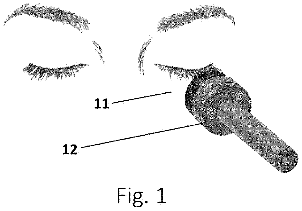
[0025]Referring first to FIG. 1, a hand piece 21 is applied to the low eyelid 22 for treatment of peri-orbital wrinkles. Alternatively other areas outside of the face or body can be treated. The hand piece can be used for treatment inside the natural openings.

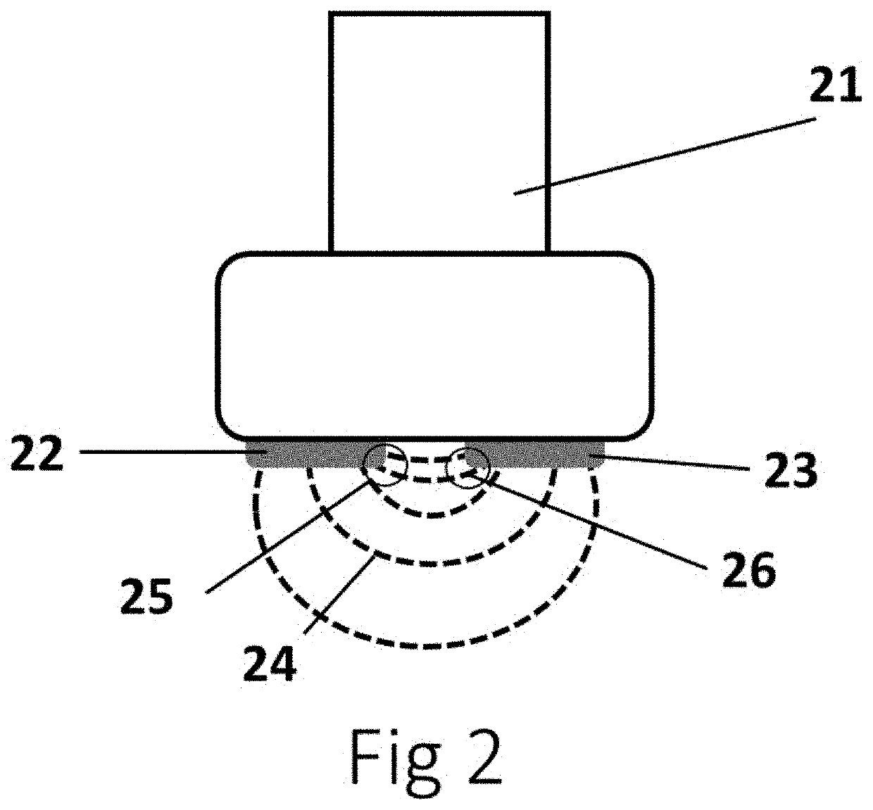
[0026]FIG. 2 shows the distribution of RF current 24 between two electrodes 22 and 23 connected to hand piece 21. RF current 24 has a higher density near the inner edges of the electrodes 22, 23 creating hot spots 25, 26. These hot spots can result in thermal damage of the tissue.

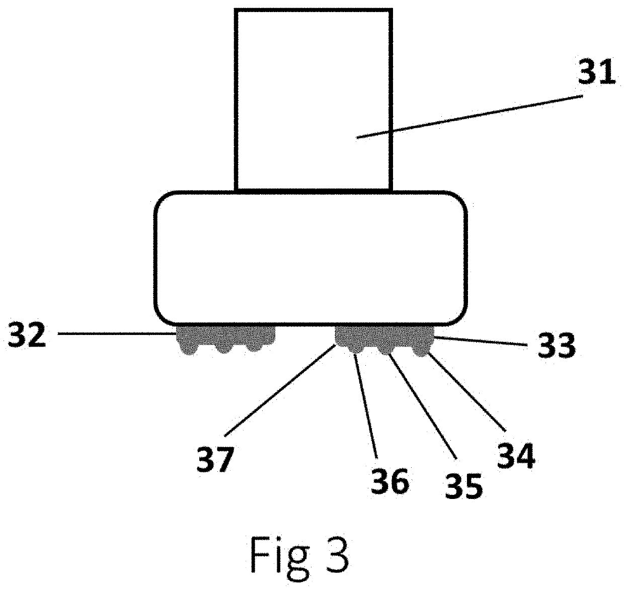
[0027]FIG. 3 shows hand piece 31 according to an embodiment of the invention with two electrodes 32, 33 applied to the treated tissue. Each electrode has an internal edge 37 and protrusions 34, 35, and 36.

[0028]FIG. 4 shows hand piece 31 according to an embodiment of the invention with two electrodes 32, 33 applied to the treated tissue. Each electrode has protrusions 34, 35, and 36. The RF current 41 concentrated on protrusions in the same way as on t...


PUM


Abstract

An applicator includes at least one RF electrode coupled to an RF generator. The at least one RF electrode has protrusions each with a curvature radius which is equal to or greater than a curvature radius of an outer edge of the at least one RF electrode.

Description

FIELD OF THE INVENTION[0001]The invention relates to a method of treatment using radio-frequency (RF) energy for non-ablative treatment of skin without hot spots.BACKGROUND OF THE INVENTION[0002]RF devices for non-ablative treatment are commonplace in medical aesthetic practice. The devices are differentiated by the type of energy application.[0003]Some of the treatments are based on moving a hand piece over the skin surface and delivering RF energy continuously. The treatment effect is achieved by elevating skin temperature during multiple passes. RF energy is delivered in continuous mode and the hand piece is moved over the treated area to reach a skin target temperature and maintain it for a required time.[0004]The other broadly used treatment option is the application of all the energy required for the treatment effect to one spot and then moving the hand piece to a new spot. Bi-polar and mono-polar RF devices are used for this type of treatment.[0005]Typically, the tissue is he...

Claims


Application Information

Patent Timeline
IPC IPC(8): A61B18/14A61B18/12
CPCA61B2018/142A61B18/148A61B2018/1253A61B2018/126A61B2018/0091A61B18/1206A61B2018/0047A61B2018/00791A61B2018/00452A61B2018/00321A61B2018/00702A61B18/14A61B2018/1417
Inventor KREINDEL, MICHAEL
Owner INMODE LTD
Why Eureka
Try Eureka