Fuel cell stack and method of producing dummy cell

a fuel cell and dummy cell technology, applied in the field of fuel cell stacks, can solve the problems of degrading the power generation stability of the fuel cell stack, no power generation is performed in the dummy cell, and low diffusion performance of the fuel gas and the oxygen-containing gas (reactant gases), so as to achieve high accuracy and efficiency, the effect of improving power generation stability

Active Publication Date: 2020-09-10
HONDA MOTOR CO LTD
View PDF0 Cites 1 Cited by
  • Summary
  • Abstract
  • Description
  • Claims
  • Application Information

AI Technical Summary

Benefits of technology

[0007]The present invention has been made in relation to the technique of this type, and an object of the present invention is to provide a fuel cell stack and a method of producing a dummy cell in which it is possible to improve power generation stability by a dummy cell which can be produced highly accurately and efficiently.

Problems solved by technology

When the temperature at the ends of the stack body becomes low due to the influence of the outside temperature, etc., there is a concern that diffusion performance of the fuel gas and the oxygen-containing gas (reactant gases) becomes low, and the power generation stability of the fuel cell stack is degraded.
Therefore, no power generation is performed in the dummy cell, and thus, no water is produced in the dummy cell.

Method used


Image

  • Fuel cell stack and method of producing dummy cell
  • Fuel cell stack and method of producing dummy cell
  • Fuel cell stack and method of producing dummy cell

Examples


Embodiment Construction

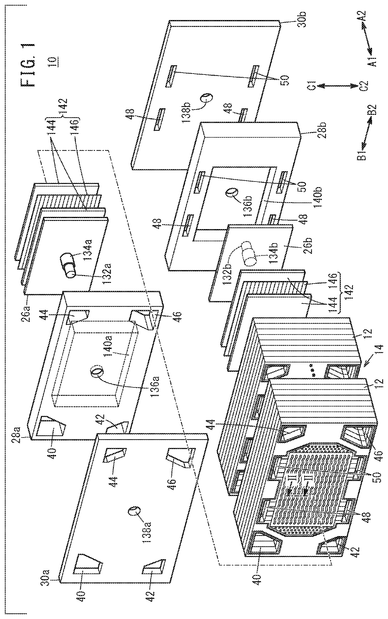
[0016]FIG. 1 is an exploded perspective view showing a fuel cell stack according to an embodiment of the present invention;

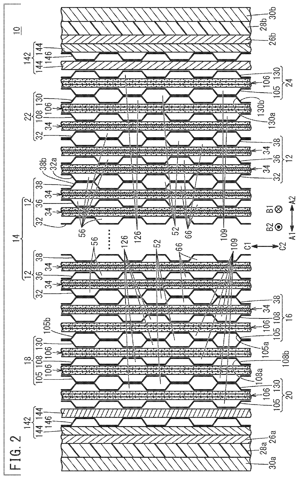
[0017]FIG. 2 is a cross sectional view taken along arrow lines II-II in FIG. 1;

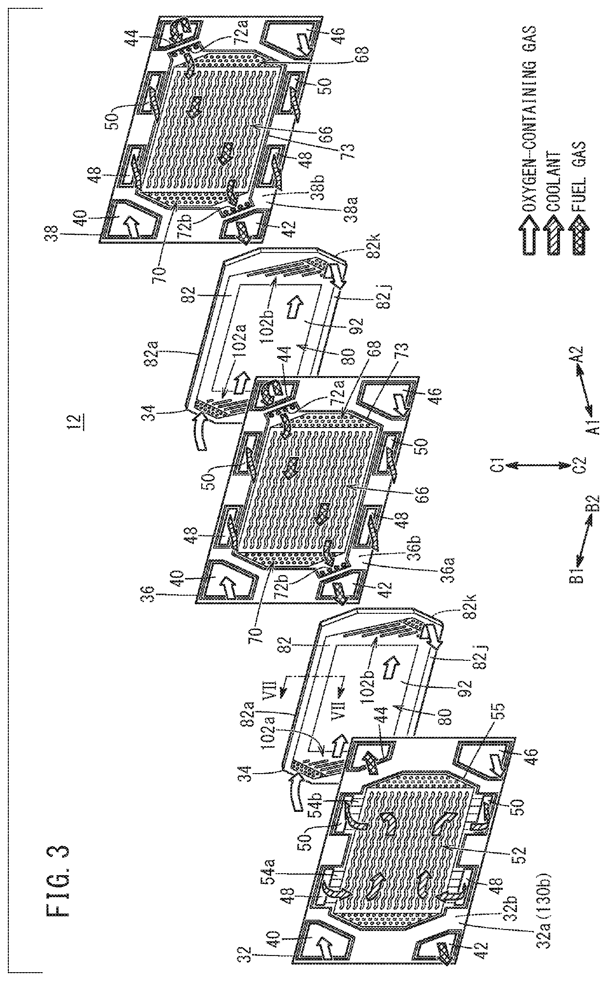
[0018]FIG. 3 is an exploded perspective view showing a power generation cell;

[0019]FIG. 4 is a front view of a first separator showing a side where an oxygen-containing gas flow field is present;

[0020]FIG. 5 is a front view of a second separator showing a side where the oxygen-containing gas flow field is present;

[0021]FIG. 6 is a front view of a third separator showing a side where a coolant flow field is present;

[0022]FIG. 7 is a cross sectional view taken along arrow lines VII-VII in FIG. 3;

[0023]FIG. 8 is a front view of a resin frame equipped dummy structural body showing a side where a first electrically conductive porous body is present;

[0024]FIG. 9 is a cross sectional view taken along arrow lines IX-IX in FIG. 8;

[0025]FIG. 10 is an exploded perspective view showing a dummy st...


PUM

PropertyMeasurementUnit
electrically conductiveaaaaaaaaaa
surface sizeaaaaaaaaaa
distanceaaaaaaaaaa

Abstract

A fuel cell stack at least includes a stack body including a plurality of power generation cells each having a membrane electrode assembly stacked in a stacking direction, and a first dummy cell provided at one end of the stack body in the stacking direction. A dummy structural body of the first dummy cell is joined to a dummy resin frame member through an adhesive layer which adheres a first outer peripheral portion and a second outer peripheral portion, and inner periphery of the dummy resin frame member to each other.

Description

CROSS-REFERENCE TO RELATED APPLICATION[0001]This application is based upon and claims the benefit of priority from Japanese Patent Application No. 2019-039503 filed on Mar. 5, 2019, the contents of which are incorporated herein by reference.BACKGROUND OF THE INVENTIONField of the Invention[0002]The present invention relates to a fuel cell stack including a stack body formed by stacking a plurality of power generation cells in a stacking direction, and a dummy cell provided at one end of the stack body in the stacking direction. Each of the power generation cells includes membrane electrode assembly and a resin frame member provided around an outer periphery of the membrane electrode assembly. Further, the present invention relates a method of producing the dummy cell.Description of the Related Art[0003]In general, a solid polymer electrolyte fuel cell employs a solid polymer electrolyte membrane (hereinafter, also simply referred to as the electrolyte membrane). The solid polymer el...

Claims


Application Information

Patent Timeline
Patent Type & Authority Applications(United States)
IPC IPC(8): H01M8/242H01M8/1004H01M8/0239H01M8/0267
CPCH01M8/1004H01M8/0267H01M8/0239H01M8/242H01M8/2465H01M8/2404H01M8/006H01M8/04701F16L59/029F16L59/02H01M8/0271H01M8/04029H01M2008/1095Y02E60/50Y02P70/50
Inventor INOUE, DAISUKE
Owner HONDA MOTOR CO LTD
Why Eureka
Try Eureka