Fiberwound tanks

a fiber-wound and well-bore technology, applied in the direction of vessel construction details, lighting and heating apparatus, heating types, etc., can solve the problem of ineffective function of the tank

Active Publication Date: 2020-09-17
AMTROL LICENSING INC
View PDF0 Cites 1 Cited by
  • Summary
  • Abstract
  • Description
  • Claims
  • Application Information

AI Technical Summary

Benefits of technology

This patent describes a fluid tank with a layer of fiber winding around its outside. This fiber winding layer helps contain any expansion of the tank caused by heat during its manufacturing process. The tank is also designed to reduce stress in the weld joint where the upper and lower walls are joined together. The technical effect of this design is an improved and reliable fluid tank that can withstand high levels of pressure and maintain its shape even during long periods of use.

Problems solved by technology

If eventually the diaphragm / bladder “bottoms out” on the tank wall, the tank becomes ineffective in the function it has been design to provide.

Method used


Image

  • Fiberwound tanks
  • Fiberwound tanks
  • Fiberwound tanks

Examples


Embodiment Construction

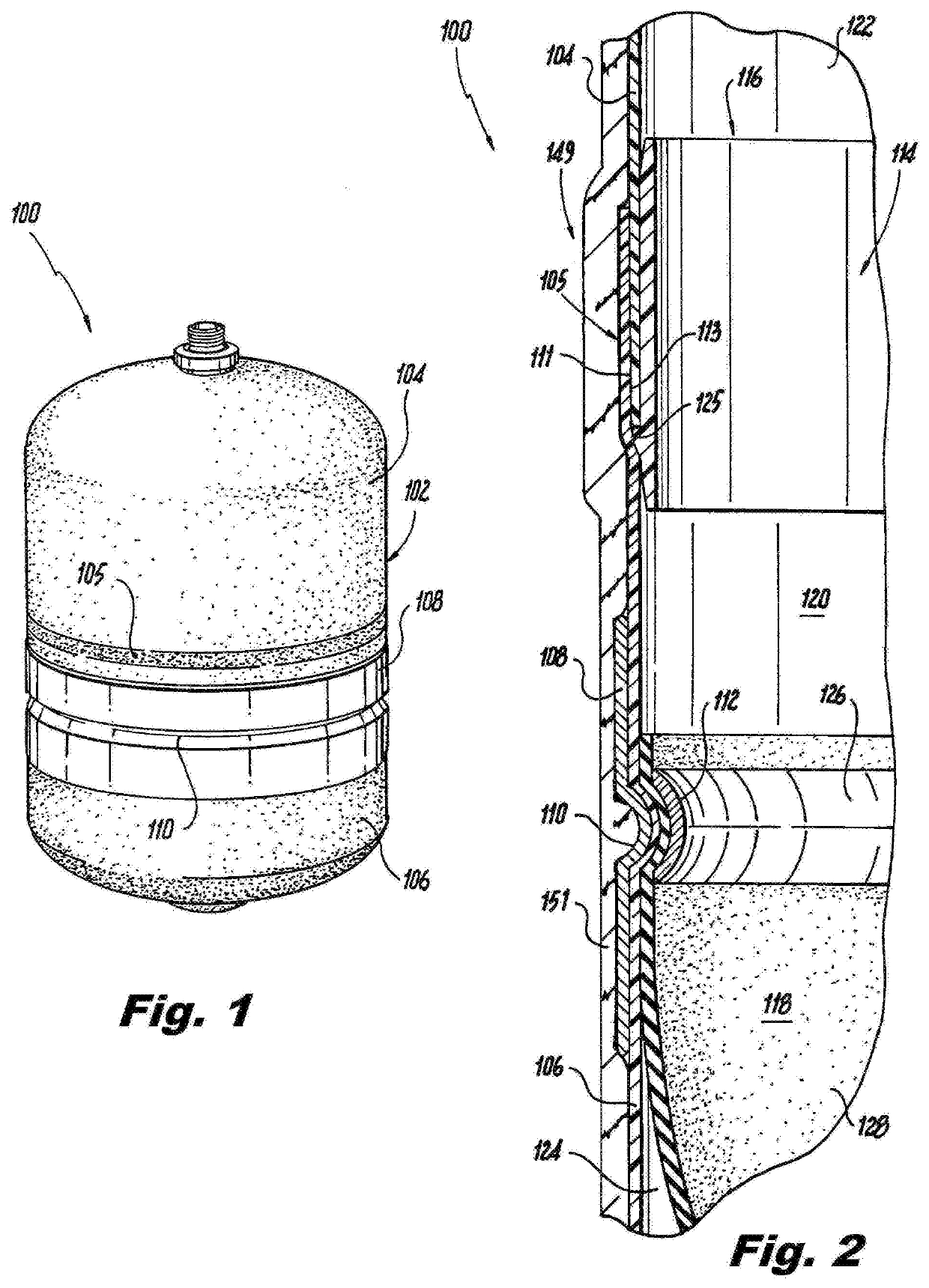
[0025]Reference will now be made to the drawings wherein like reference numerals identify similar structural features or aspects of the subject invention. For purposes of explanation and illustration, and not limitation, a partial view of an exemplary embodiment of the fluid tank in accordance with the invention is shown in FIG. 1 and is designated generally by reference character 100. Other embodiments of the fluid tank 100 in accordance with the invention, or aspects thereof, are provided in FIGS. 2-8 as will be described.

[0026]As shown in FIGS. 1 and 2, fluid tank 100 includes polymeric liner 102 comprising an upper wall 104 and a lower wall 106. Polymeric liner 102 can be a thermoplastic liner, for example. Upper wall 104 and lower wall 106 define a cavity 114 therebetween. Fluid tank 100 is an expansion tank, e.g. a Type IV fiberwound tank. Liner 102 can be made from a variety of polymeric materials, for example, high-density polyethylene (HDPE). HDPE provides permeation resist...


PUM


Abstract

A fluid tank includes polymeric liner comprising an upper wall and a lower wall. The upper wall and the lower wall define a cavity therebetween. A weld joint joins the upper and lower walls together. A method for assembling a fluid tank includes overlapping surfaces of an upper wall and a lower wall to form a liner defining a cavity. The method includes joining the surface of the upper wall and the surface of the lower wall together by welding to form a weld joint between the upper wall and the lower wall. The method can include cooling the weld joint to control warpage of the liner at the weld joint.

Description

BACKGROUND1. Field of the Invention[0001]The present invention generally relates to well and expansion tanks and, more particularly, to fiberwound well and expansion tanks.2. Description of Related Art[0002]Many well and expansion tanks use a diaphragm or bladder to separate air from water. An air charge pressure on one side keeps the diaphragm / bladder at a distance away from the inside wall of the tank in the air dome. When the tank is installed onto a water system, the water system pressure pushes back against the diaphragm / bladder, compressing the air. The proper pre-charge will continue to keep the diaphragm / bladder away from the tank wall. If the pre-charge pressure is not enough to provide an air volume appropriate for the water supply pressure, the diaphragm / bladder will fill the air cell. If eventually the diaphragm / bladder “bottoms out” on the tank wall, the tank becomes ineffective in the function it has been design to provide. An example of a non-metallic conventional exp...

Claims


Application Information

Patent Timeline
Patent Type & Authority Applications(United States)
IPC IPC(8): F17C1/16F15B1/10F17C1/06F16J12/00F24D3/10
CPCF17C2201/0185F15B1/106F17C2203/0663F15B1/22F24D3/1016F17C1/06F15B2201/605F17C2209/221F17C2203/066F15B2201/4053F17C2201/0109F17C2203/0673F17C2205/0302F17C2203/0604F15B2201/615F15B2201/205F17C2203/0619F15B2201/4056F15B1/14F15B2201/3151F16J12/00F17C1/16Y02A20/00
Inventor VAN HAAREN, CHRISTOPHER A.JEANNOTTE, JOSEPHKAMPF, CHRISTOPHERGOUDAS, ALEXANDER
Owner AMTROL LICENSING INC
Why Eureka
Try Eureka