
Machine tool

a technology of machine tools and workpieces, applied in the field of machine tools, can solve the problems of reducing the precision of machining, affecting the quality of workpieces, so as to improve the precision of workpieces, reduce errors, and increase precision

Active Publication Date: 2020-09-24
HYUNDAI WIA
View PDF0 Cites 1 Cited by
  • Summary
  • Abstract
  • Description
  • Claims
  • Application Information

AI Technical Summary

Benefits of technology

The present invention is a machine tool that can perform machining in multiple directions and has a tilting and rotating table. The machine tool has symmetrically formed structures, which increase precision and minimize errors. The machine tool has a simplified structure and reduced manufacturing cost due to the functions of the base. The machine tool has minimal displacement and maximizes dynamic performance, increasing productivity. The machine tool is easy to handle and access, and can accommodate heavy workpieces without interference. The technical effects of the machine tool include improved precision, reduced errors, and maximized productivity.

Problems solved by technology

As described above, since the necessary structures are not integrated and coupled to one another through additional couplers, vibration or thermal displacement generated by the spindle are not sufficiently removed and influence the entire structure, which causes a problem that the machining precision decreases.
Such overlap displacement is usually generated by complex reasons including vibration and thermal influence during a machining process.
When overlap displacement is generated, it greatly influences the positioning accuracy between the front end of a tool mounted on a spindle and the machining center of a workpiece on a table, which is the main factor that deteriorates the quality of the workpiece.
Further, such overlap displacement is large and generated more irregularly, as the machining speed and the cutting amount are increased, and there is a limit in removing the overlap displacement only using additional means.

Method used


Image

  • Machine tool
  • Machine tool
  • Machine tool

Examples


Embodiment Construction

[0031]A machine tool according to an exemplary embodiment of the present invention is described hereafter with reference to the accompanying drawings.

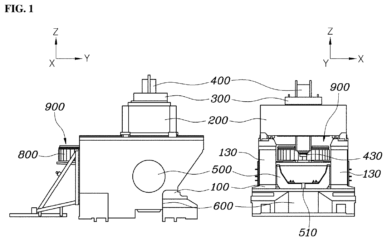
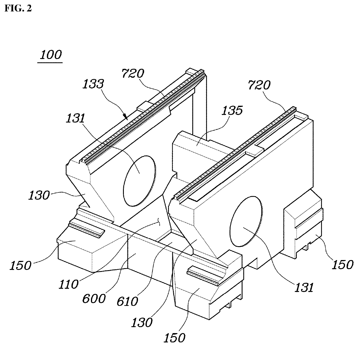
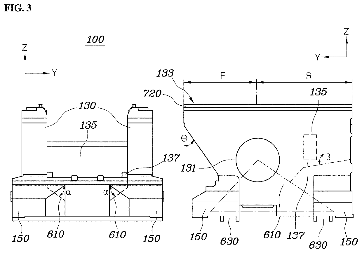
[0032]FIG. 1 is a view showing a machine tool according to an embodiment of the present invention, FIG. 2 is a view showing a base 100 of FIG. 1, and FIG. 3 is a front and side view of FIG. 2. Further, FIG. 4 is a view showing a saddle 200 of FIG. 1, FIG. 5 is a view showing a crosspiece 300 of FIG. 1, and FIG. 6 is a view showing a vertical ram 400 of FIG. 1.

[0033]A first axis may be a Y-axis, a second axis may be an X-axis, and a third axis may be a Z-axis in this description, but the directions can be freely changed, depending on the design or environment, so they are referred to as the first axis, the second axis, and the third axis in this specification.

[0034]As shown in FIGS. 1 and 2, a machine tool according to an embodiment of the present invention includes: a base 100 having a mounting space 110 inside, in which a workpiece is...


PUM

PropertyMeasurementUnit
Angleaaaaaaaaaa
Angleaaaaaaaaaa

Abstract

Disclosed is a machine tool including: a base having a pair of first-axial slides facing each other at both sides of a mounting space; a saddle coupled to the first-axial slides of the base to slide in a first axis direction and having a pair of second-axial slides facing each other; a crosspiece coupled to the second-axial slides of the saddle to slide in a second axis direction and having a pair of third-axial slides facing each other; a vertical ram coupled to the third-axial slides of the crosspiece to slide in a direction perpendicular; and a table disposed in the mounting space of the base to be able to rotate relative to the base.

Description

TECHNICAL FIELD[0001]The present invention relates to a machine tool and, more particularly, to a machine tool that has a simple structure because it is a mono-block type in which a bed and a column are integrated and that can perform high-accuracy / high-speed machining by minimizing vibration and thermal displacement.BACKGROUND ART[0002]In general, a machine tool means equipment that cuts workpieces by moving in three axial directions with respect to a spindle. Recently, the shapes required for workpieces become more complicated, but a demand for improving productivity to be able to produce complicated shapes within a short time by minimizing the time that is used for machining is increased. Accordingly, a demand has rapidly increased for a 5-axis machining tool can tilt and rotate a table in addition to performing 3-axis machining.[0003]A 5-axis machine tool generally includes: three linear axes X, Y, and Z arranged perpendicularly at a machining center point (TCP) that is a so-cal...

Claims


Application Information

Patent Timeline
IPC IPC(8): B23Q3/155
CPCB23Q3/1556B23C2220/32B23Q2701/02B23Q2701/04B23Q1/017B23Q1/626B23Q1/015Y10T408/935Y10T483/1733Y10T409/30896Y10T409/309632
Inventor LEE, DAL HOKORFF, DENNISNOWAK, ERIKSPENGLER, SEBASTIANKIM, JE WANGJALIZI, BEHZADSIEBER, MARCHOERNER, JOHANNESSCHNEIDER, THOMASHAN, SANG MOOK
Owner HYUNDAI WIA
Learn More