
Container and method for preserving a tissue sample

a tissue sample and container technology, applied in the field of container for in vitro diagnostics, can solve the problems of preventing the passage of formaldehyde and containing risks for the health of operators, and achieve the effect of reducing the number of component parts and small chance of error

Pending Publication Date: 2020-10-08
BICOCCHI ENRICO
View PDF6 Cites 1 Cited by
  • Summary
  • Abstract
  • Description
  • Claims
  • Application Information

AI Technical Summary

Benefits of technology

The present invention aims to minimize risks of exposure to harmful substances during the transfer and deposition of tissue into a diagnostic container in vitro. It also aims to provide a container with a reduced number of component parts, avoid the presence of shredded film scraps that can create an obstacle to the passage of the formaldehyde solution, and provide a method of using the container with the aforementioned purposes that is intuitive and leaves small chance of error by those who work for storing and transporting a tissue sample to be subjected to histopathological examinations.

Problems solved by technology

In the diagnostic routine it is evident that the major problem in the use of formaldehyde is the containment of risks to the health of the operators, since formaldehyde was classified according to EU regulation 1272 / 2008 as an “Acute Tox 3” substance—substance with acute Category 3 toxicity by ingestion, skin contact and inhalation, and as a “Canc 2” substance—carcinogenic suspected substance.
The formaldehyde flows from the upper receptacle to the lower receptacle along the through holes made in the base of the cap; there is a drawback that the air, present in the lower receptacle, having to pass into the upper receptacle, hinders the passage of the formaldehyde.
In addition to air, the pierced film can create an obstacle to the passage of the formaldehyde from the upper receptacle to the lower receptacle.

Method used


Image

  • Container and method for preserving a tissue sample
  • Container and method for preserving a tissue sample
  • Container and method for preserving a tissue sample

Examples


Embodiment Construction

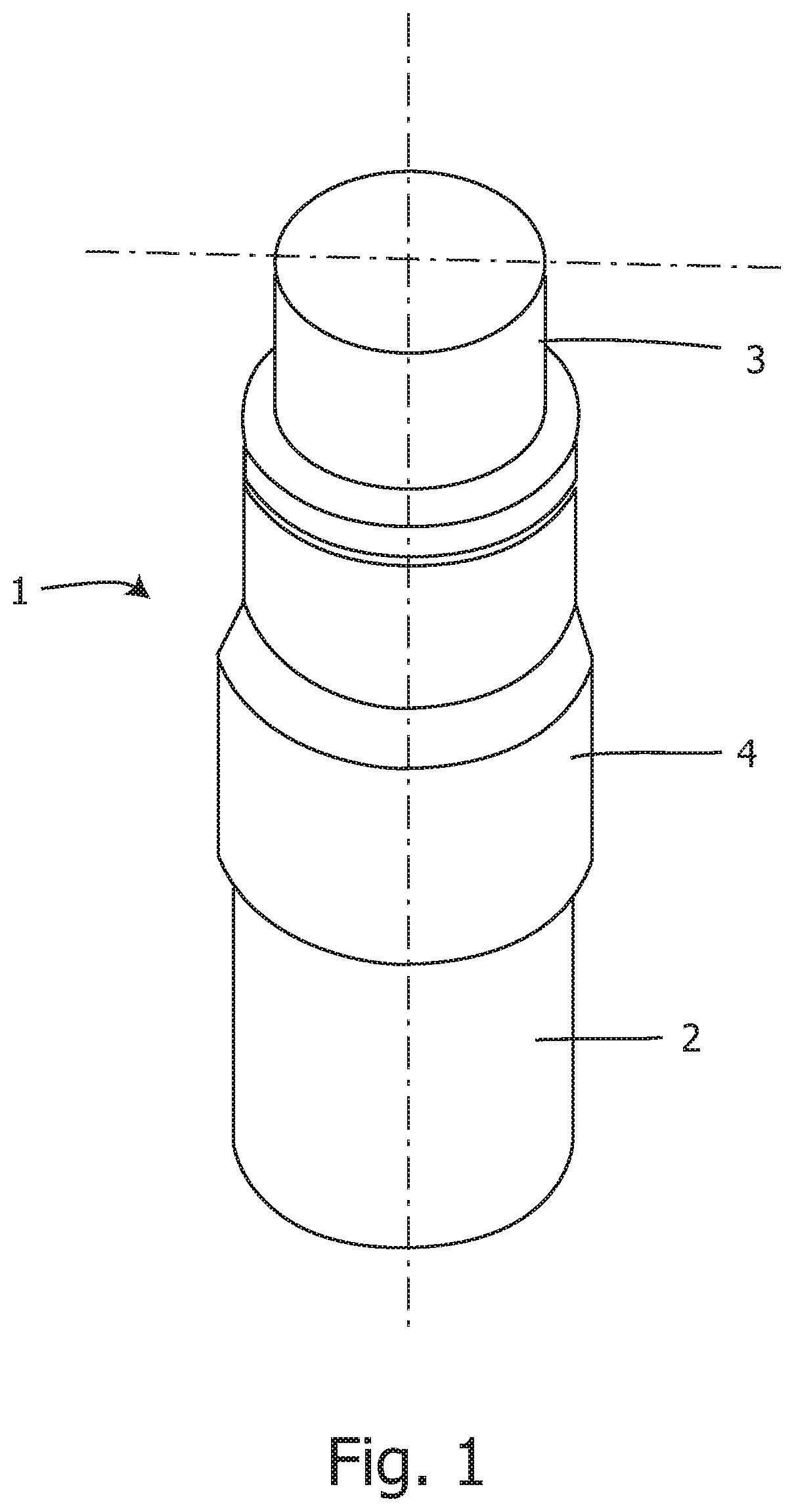
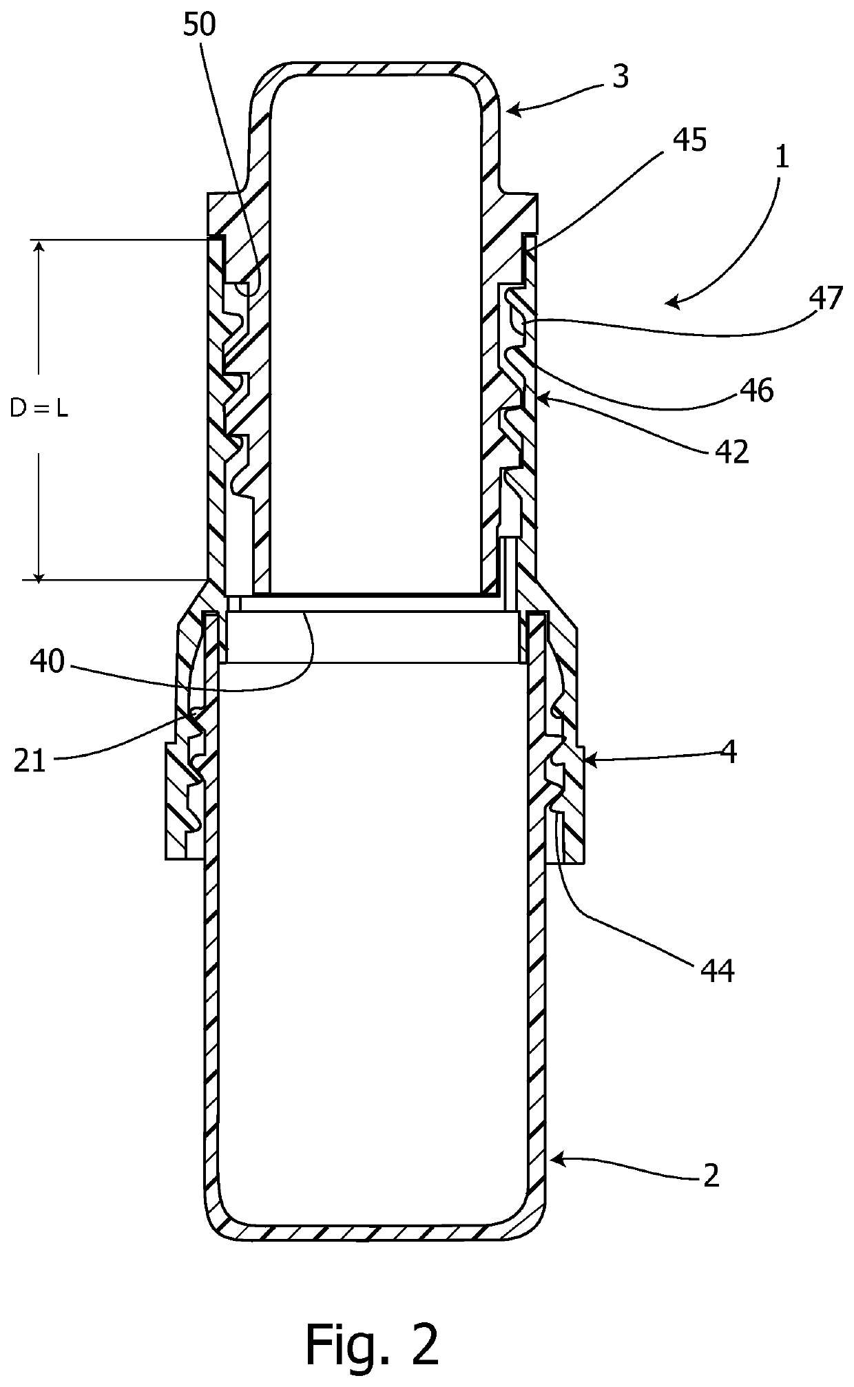
[0032]First of all, reference is made to FIGS. 1 and 2 which are an overall perspective view and a central longitudinal sectional view in a closed position, respectively, of a first embodiment of the container 1 for in vitro diagnostic according to the present invention.

[0033]The container 1 consists of a lower receptacle 2, an upper receptacle 3 and a connecting sleeve 4, the latter as a threaded coupling means for joining the lower receptacle 2 to the upper receptacle 3. The terms “lower” and “upper” refer to the upright position of the container in its handling, because when the container is completely closed it can assume any position without any prejudice.

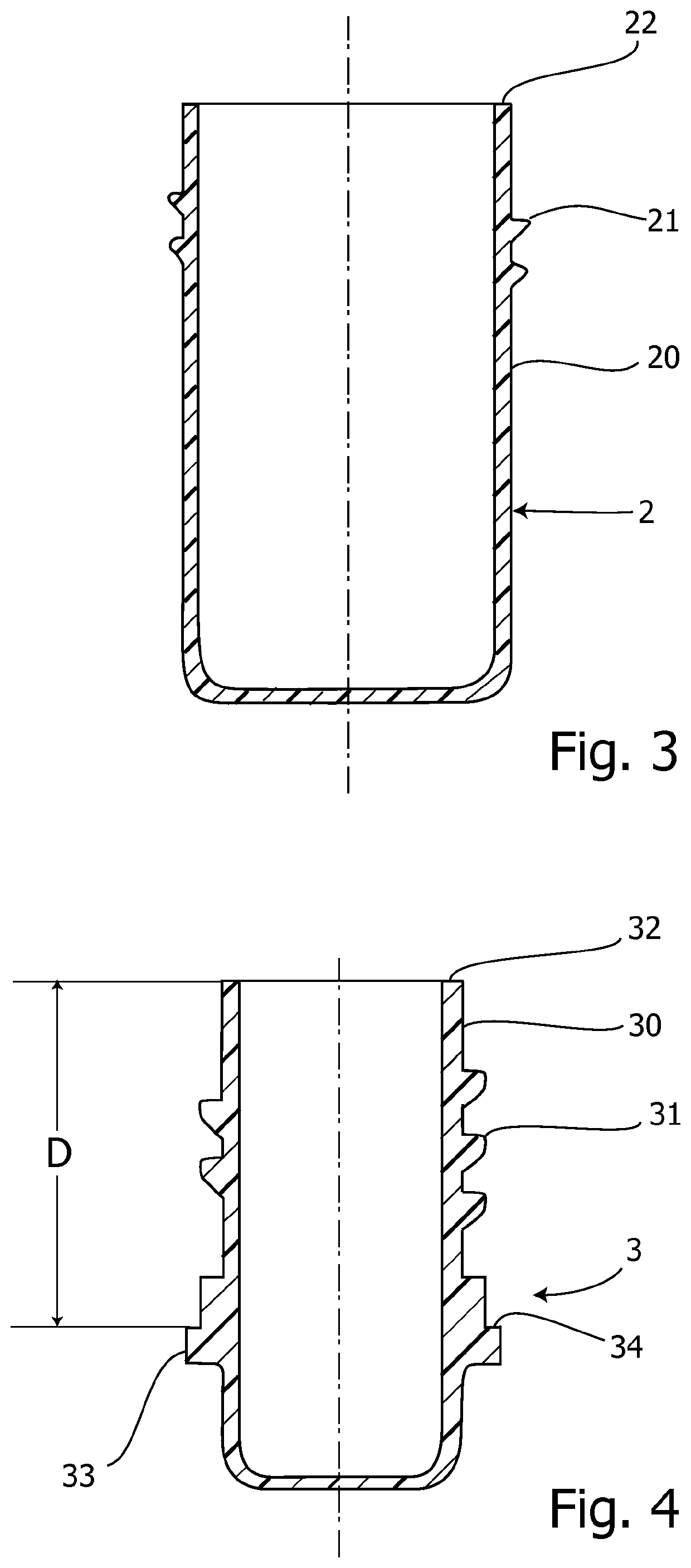
[0034]The lower receptacle 2 is designed to contain, before using the container, a non-toxic liquid, for example a buffer solution of the kind used to receive a tissue sample. As shown in the longitudinal sectional view in FIG. 3, the lower receptacle 2 has a side wall 20 provided with an external thread 21 and ending with a c...


PUM

PropertyMeasurementUnit
diameteraaaaaaaaaa
lengthaaaaaaaaaa
timeaaaaaaaaaa

Abstract

A container (1) for in vitro diagnostic has a lower receptacle (2) designed to contain a non-toxic liquid (LS), an upper receptacle (3) designed to contain a toxic liquid (LF), and a connecting sleeve (4), in a threaded coupling with the lower receptacle (2) and the upper receptacle (3) for butt joining them. The connecting sleeve (4) has a transversal septum (40) being provided with a plurality of passage openings (48) and vent openings (49). When the container (1) is completely closed, both the lower receptacle (2) and the upper receptacle (3) abut the transversal septum (40). If the upper receptacle (3) is partially unscrewed with respect to the transversal septum (40), the toxic liquid (LF) flows by gravity into the lower receptacle (2). A method for storing a sample of human or animal tissue by using the container (1) is also provided.

Description

TECHNICAL FIELD[0001]The present invention relates to a container for in vitro diagnostic. The invention can be used, more specifically, in diagnostic histopathology. The container is of the single use type. The invention also relates to a method for storing and transporting a sample of human or animal tissue.BACKGROUND ART[0002]More in detail, such a container is used for the secure fixation, storage and transport of human or animal tissues or parts thereof to be subjected to specific histological, immunohistochemical and molecular biology laboratory tests. The tissue samples taken in vivo are immersed in a suitable fixative-preservative reagent in order to inhibit degradation processes and keep the architectural and macromolecular structure of the tissues intact.[0003]To date, liquids containing formaldehyde in buffered solution are considered optimal fixative-preservatives. In the diagnostic routine it is evident that the major problem in the use of formaldehyde is the containmen...

Claims


Application Information

Patent Timeline
Patent Type & Authority Applications(United States)
IPC IPC(8): C12M3/00C12M1/02C12M1/00
CPCC12M21/08C12M23/44C12M27/00C12M29/20A61B10/0096
Inventor BICOCCHI, ENRICO
Owner BICOCCHI ENRICO
Learn More