Beam for a wind turbine blade, wind turbine blade, wind turbine, method for manufacturing a beam for a wind turbine blade and method for manufacturing a wind turbine blade

a technology for wind turbine blades and beams, which is applied in the manufacture of final products, machines/engines, wind turbine blades, etc., can solve the problems of wind turbine blade failure, high specific modulus composite materials are typically more expensive and more difficult to manufactur

Active Publication Date: 2020-10-08
SIEMENS GAMESA RENEWABLE ENERGY AS
View PDF0 Cites 1 Cited by
  • Summary
  • Abstract
  • Description
  • Claims
  • Application Information

AI Technical Summary

Benefits of technology

[0007]The beam according to embodiments of the invention may be used in any technical application, the preferable application being a wind turbine blade (also known as rotor blade) of a wind turbine. The beam comprises multiple longitudinal beam portions in its at least one recessed longitudinal end section, whereby the line loads from the beam can be favorably transferred through the longitudinal beam portions. Thereby, when releasing the load from the longitudinal beam portions instead of an unrecessed beam, the risk of failure of the shell or the component of the wind turbine blade, to which the beam is attached, can be reduced. Moreover, the beam according to embodiments of the invention is very flexible due to the at least one longitudinal recess and thereby has high twist capabilities, meaning that it can be twisted to a high degree without failure. Further, the beam of embodiments of the invention can be manufactured very cost-efficiently.
[0024]In a preferred embodiment of the invention, the beam is attached to the shell and / or the spar comprising the beam is arranged in the wind turbine blade at the trailing edge or within a distance of up to 30%, in particular 20% and more particularly 10% of a width of the wind turbine blade from the trailing edge. Here, the high twist capabilities and load transfer capabilities of the beam are particularly well facilitated.

Problems solved by technology

Such composite materials of high specific modulus are typically more expensive and more challenging when arranging them in wind turbine blades compared to materials having a lower specific modulus.
When releasing the load from the beam to the shell or another component of the wind turbine blade, to which the beam is attached, the line loads applied from longitudinal ends of the beam to the shell or the other component of the wind turbine blade are very high and may cause failure of the wind turbine blade.

Method used


Image

  • Beam for a wind turbine blade, wind turbine blade, wind turbine, method for manufacturing a beam for a wind turbine blade and method for manufacturing a wind turbine blade
  • Beam for a wind turbine blade, wind turbine blade, wind turbine, method for manufacturing a beam for a wind turbine blade and method for manufacturing a wind turbine blade
  • Beam for a wind turbine blade, wind turbine blade, wind turbine, method for manufacturing a beam for a wind turbine blade and method for manufacturing a wind turbine blade

Examples


first embodiment

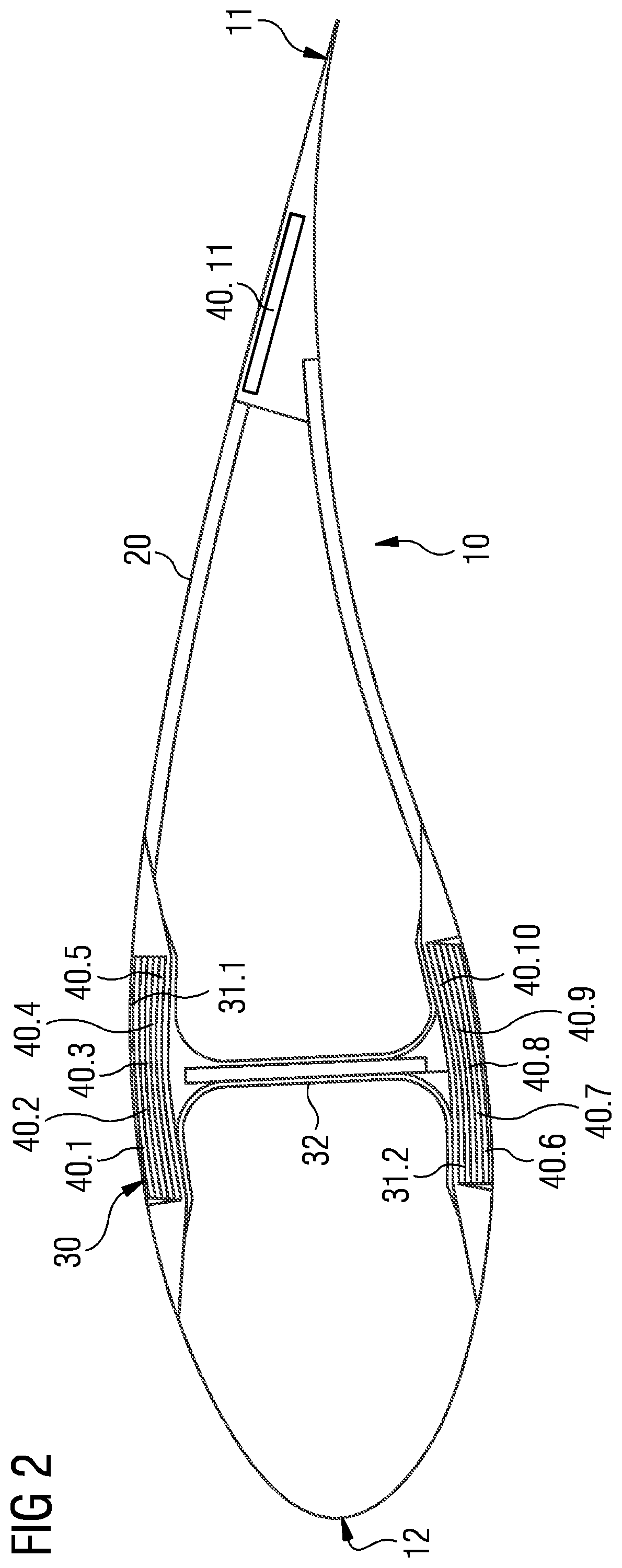
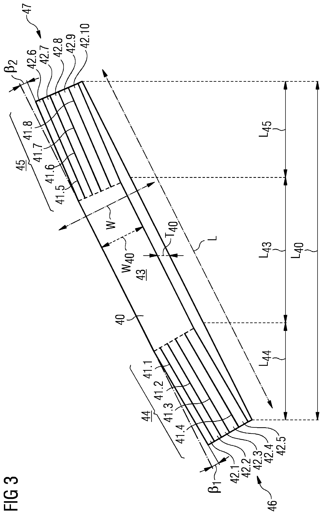
[0038]FIG. 3 is a side perspective view on a beam 40 according to embodiments of the invention. Such a beam 40 may be used as one, several or all of the beams 40.1, 40.2, 40.3, 40.4, 40.5, 40.6, 40.7, 40.8, 40.9, 40.1, 40.11 in the wind turbine blade 10 of FIG. 2. In this particular embodiment, the beam 40 is a pultruded element made from carbon fiber-reinforced plastic.

[0039]The beam 40 has a longitudinal mid-section 43, a first recessed longitudinal end section 44 and a second recessed longitudinal end section 45. The longitudinal mid-section 43 is arranged in between the first recessed longitudinal end section 44 and the second recessed longitudinal end section 45. The first recessed longitudinal end section 44 extends to a first longitudinal end 46 of the beam 40 and the second recessed longitudinal end section 45 extends to a second longitudinal end 47 of the beam 40. The length of the beam 40 is the sum of the length L43 of the longitudinal mid-section 43, the length L44 of th...

second embodiment

[0043]FIG. 4 is a side perspective view on a portion of a beam 40 according to embodiments of the invention. Ten longitudinal recesses 41.1, 41.2, 41.3, 41.4, 41.5, 41.6, 41.7, 41.8, 41.9, 41.10 are arranged parallel to one another in the longitudinal direction of the beam 40, whereby the longitudinal recesses 41.1, 41.2, 41.3, 41.4, 41.5, 41.6, 41.7, 41.8, 41.9, 41.10 separate the beam 40 into eleven adjacent longitudinal beam portions 42.1, 42.2, 42.3, 42.4, 42.5, 42.6, 42.7, 42.8, 42.9, 42.10, 42.11. The longitudinal recesses 41.1, 41.2, 41.3, 41.4, 41.5, 41.6, 41.7, 41.8, 41.9, 41.10 and the longitudinal beam portions 42.1, 42.2, 42.3, 42.4, 42.5, 42.6, 42.7, 42.8, 42.9, 42.10, 42.11 have the tapered thickness T40 of the beam 40 at their respective location. The longitudinal recesses 41.1, 41.2, 41.3, 41.4, 41.5, 41.6, 41.7, 41.8, 41.9, 41.10 are arranged in the first recessed longitudinal end section 44 having the first longitudinal end 46. The second longitudinal end 47 of the...


PUM


Abstract

Provided is a beam for a wind turbine blade of a wind turbine, whereby the beam is made from a composite material including a matrix and a reinforcement. The beam includes at least one recessed longitudinal end section in which the beam includes at least one longitudinal recess arranged in a longitudinal direction or substantially a longitudinal direction of the beam extending from a longitudinal mid-section of the beam to a longitudinal end of the beam, so that the at least one longitudinal recess separates the beam into adjacent longitudinal beam portions, whereby the longitudinal beam portions are attached to the longitudinal mid-section.

Description

CROSS-REFERENCE TO RELATED APPLICATIONS[0001]This application claims priority to European Application No. 19167473.8, having a filing date of Apr. 5, 2019, the entire contents of which are hereby incorporated by reference.FIELD OF TECHNOLOGY[0002]The following is directed to a beam for a wind turbine blade of a wind turbine, whereby the beam is made from a composite material comprising a matrix and a reinforcement. The following is further directed to a wind turbine blade for a wind turbine and a wind turbine. Moreover, the following is directed to a method for manufacturing a beam for a wind turbine blade of a wind turbine and a method for manufacturing a wind turbine blade of a wind turbine.BACKGROUND[0003]Wind turbine blades must be able to efficiently convert wind into spinning movement of the wind turbine blades, so that energy of the wind can be converted into rotary mechanical movement of a rotor to which the wind turbine blades are attached. It is preferable, to use material...

Claims


Application Information

Patent Timeline
Patent Type & Authority Applications(United States)
IPC IPC(8): F03D1/06F01D5/28
CPCF01D5/282F03D1/0633F03D1/0675F03D13/10F03D80/00F05B2280/6003Y02P70/50Y02E10/72
Inventor HENRICHSEN, SOEREN RANDRUP DAUGAARDNIELSEN, MOGENS
Owner SIEMENS GAMESA RENEWABLE ENERGY AS
Why Eureka
Try Eureka