Heat exchanger pipe, method of manufacturing heat exchanger pipe, heat exchanger fin, elliptical heat exchanger pipe, and hot water storage type heat exchanger having elliptical heat exchanger pipe

a technology of heat exchanger and heat exchanger fin, which is applied in the field of heat exchanger, can solve the problems of poor half shell productivity, insufficient thermal contact amount between the fluid, the heat source and the ribs, etc., and achieve the effects of preventing the leakage of condensate water through at least the ends, preventing the separation between the outer pipe and the heat exchanger fin, and increasing the heat transfer area

Pending Publication Date: 2020-10-08
CHOI OK
View PDF1 Cites 3 Cited by
  • Summary
  • Abstract
  • Description
  • Claims
  • Application Information

AI Technical Summary

Benefits of technology

[0039]Further, since ends are integrally formed, sealing is secured at the portion. Accordingly, leakage of condensate water through at least the ends is completely prevented.
[0040]Further, the elliptical heat exchanger pipe provides a heat exchanger pipe having an elliptical cross-section. Accordingly, a heat transfer area is increased in comparison to heat exchanger pipes having the same size of outer pipe and different shapes. Further, separation between the outer pipe and the heat exchanger fin is prevented when the heat exchanger fin is inserted into the outer pipe to be in close contact therewith.
[0041]Further, some of the heat exchanger fins of the elliptical heat exchanger are discontinuous type heat exchanger fins and the others are continuous type heat exchanger fins without disconnection, thereby providing a complex configuration.
[0042]Accordingly, the heat exchange rate is increased by the discontinuous type heat exchanger fins and deformation of the heat exchanger tube is fundamentally prevented by the reinforcing force provided by the continuous type heat exchanger fins, so it is not required to improve the processes or add processes in order to prevent deformation, thereby improving productivity.
[0043]Meanwhile, in the hot water storage type heat exchanger of the present invention, elliptical heat exchanger pipes having a large heat transfer area is disposed at the outer portion in the end plate having a large circumference and the circular heat exchanger pipes having a small heat transfer area are disposed at the center of the end plate having a small circumference, thereby providing a complex array of heat exchanger pipes.
[0044]Accordingly, it is possible to considerably increase the heat transfer area by the heat exchanger pipe to the outer diameter of the entire heat exchanger and a relatively small number of heat exchanger pipes are used to provide the same thermal efficiency, so it is possible to reduce the size of the heat exchanger.

Problems solved by technology

However, according to this related art, the lengths of the ribs 1005 are adjusted such that their ends are aligned, so the fluid flowing through the tube makes monotonous flow, and accordingly, there is a problem that the thermal contact amount between the fluid, which is a heat source, and the ribs 1005 is not sufficient.
Accordingly, since it is required not only to extrude the two half shells 1003 and 1004, but also to cut the formed two half shells 1003 and 1004 into predetermined lengths, there is a problem that productivity of the half shells is poor.
Further, the two half shells 1003 and 1004 are separately formed and the assembled in the outer tube 1001, in which it is very difficult to keep the half shells 1003 and 1004 aligned with each other, so there is a problem that productivity of a heat exchange tube is also poor.
Further, since the two half shells 1003 and 1004 are completely separately provided, there is a possibility of leakage through the joints at both sides.
When sealing is poor, there is a possibility of leakage of condensate water with condensation of high-temperature combustion gas.

Method used


Image

  • Heat exchanger pipe, method of manufacturing heat exchanger pipe, heat exchanger fin, elliptical heat exchanger pipe, and hot water storage type heat exchanger having elliptical heat exchanger pipe
  • Heat exchanger pipe, method of manufacturing heat exchanger pipe, heat exchanger fin, elliptical heat exchanger pipe, and hot water storage type heat exchanger having elliptical heat exchanger pipe
  • Heat exchanger pipe, method of manufacturing heat exchanger pipe, heat exchanger fin, elliptical heat exchanger pipe, and hot water storage type heat exchanger having elliptical heat exchanger pipe

Examples


first embodiment

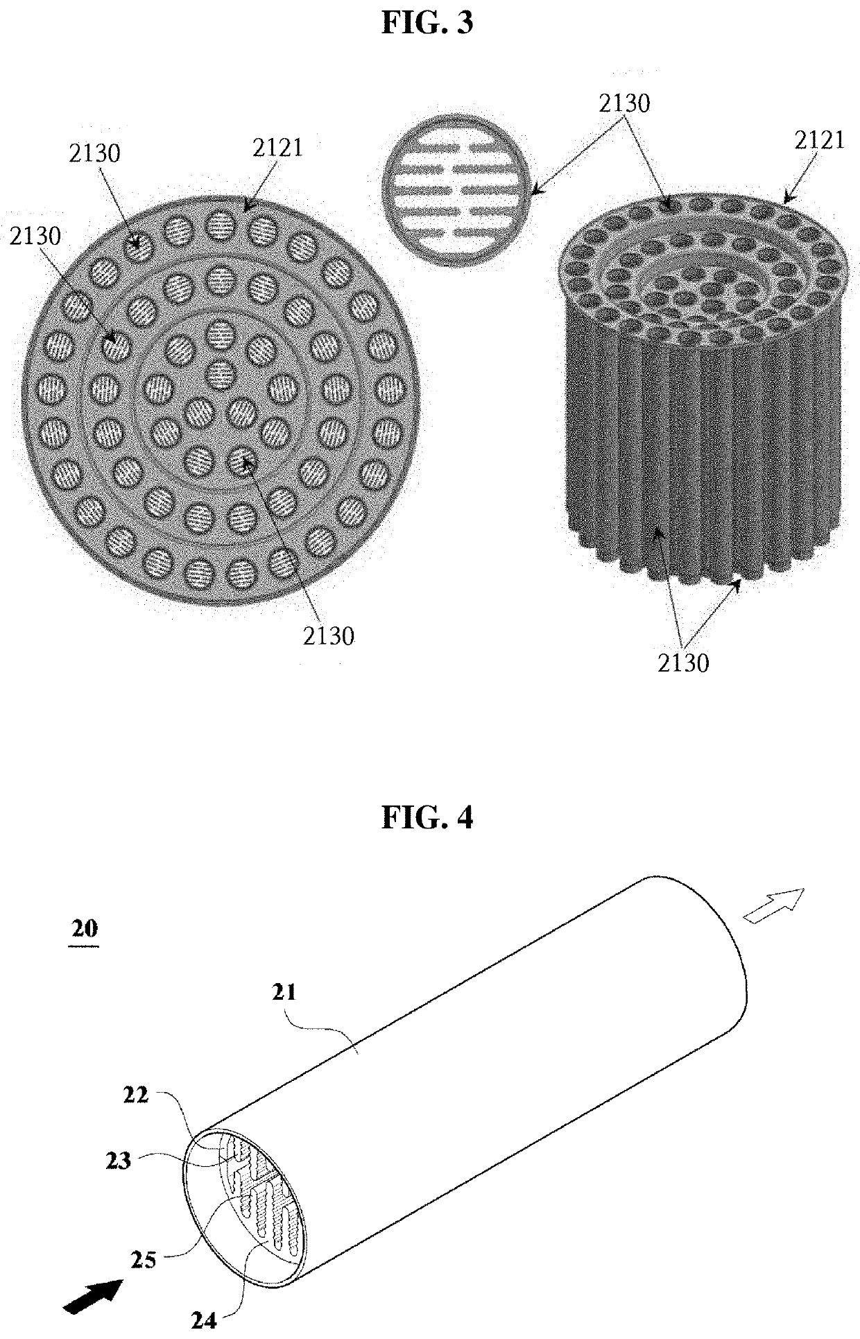
[0067]First, a heat exchanger pipe 20 according to the present invention, as shown in the perspective view of FIG. 4 and the cross-sectional view of FIG. 5, includes an outer pipe 21 formed in a cylindrical shape, a first half insert 22, 23 and a second half insert 24, 25 that are inserted in the outer pipe 21. For example, the outer pipe 21 may be made of a metal material such as steel, and the first half insert 22, 23 and the second half insert 24, 24 may be made of an aluminum material.

[0068]The first half insert 22, 23 is composed of a first half shell 22 formed in a semi-cylinder shape obtained by longitudinally cutting a cylinder, and a plurality of first ribs 23 disposed in the first half shell 22 and having long fin shapes. Similarly, the second half insert 24, 25 is composed of a second half shell 24 and a plurality of second ribs 25.

[0069]Ends F of the first half shell 22 and ends F′ of the second half shell 24 are flat surfaces, so when the first half shell 22 and the sec...

second embodiment

[0080]Hereafter, a heat exchanger pipe according to the present invention is described with reference to the accompanying drawings.

[0081]FIG. 6 is a cross-sectional view showing a heat exchanger pipe according to a second embodiment of the present invention.

[0082]As shown in FIG. 6, a heat exchanger pipe 30 according to a second embodiment of the present invention includes an outer pipe 31 formed in a cylindrical shape, and a first half insert 32, 33 and a second half insert 34, 35 that are inserted in the outer pipe 31.

[0083]The first half insert 32, 33 is composed of a first half shell 32 and a plurality of first ribs 33 and the second half insert 34, 35 is composed of a second half shell 34 and a plurality of second ribs 35. This configuration is the same as that of the first embodiment of the present invention described above.

[0084]However, in the heat exchanger pipe according to the second embodiment of the present invention, the first ribs 33 include a first-first rib 33a to a...

third embodiment

[0087]FIGS. 7A and 7B are cross-sectional views showing a heat exchanger pipe according to the present invention.

[0088]As shown in FIGS. 7A and 7B, a heat exchanger pipe according to a third embodiment of the present invention includes a first half insert 22, 23 and a second half insert 24, 25 that are inserted in an outer pipe (see 21 in FIG. 2) formed in a cylindrical shape. The first half insert 22, 23 is composed of a first half shell 22 and a plurality of first ribs 23 and the second half insert 24, 25 is composed of a second half shell 24 and a plurality of second ribs 25. This configuration is the same as that of the first embodiment of the present invention described above.

[0089]However, the third embodiment of the present invention has a different in that first bending portions 22a and second bending portions 24a for assembly are respectively formed at both end portions of the first half shell 22 and at both end portions of the second half shell 24, and the first bending po...


PUM


Abstract

The present invention relates to a heat exchanger pipe enabling heat exchange between fluid flowing through the pipe and fluid existing outside the pipe, and a method of manufacturing the heat exchanger pipe. In particular, the present invention relates to a heat exchanger pipe that improves a heat exchange rate by making flow of fluid through the pipe more active and increasing a contact amount, that has an improved contact characteristic and a sealing characteristic between an outer pipe and an insert inserted in the outer pipe in the process of manufacturing, and that is easily manufactured; and a method of manufacturing the heat exchanger pipe.

Description

CROSS-REFERENCE TO RELATED APPLICATIONS[0001]This application is a continuation-in-part of U.S. patent application Ser. No. 14 / 373,383, filed on Jul. 21, 2014, which is a National Stage Entry of International Patent Application No. PCT / KR2012 / 007404, filed on Sep. 17, 2012, which claims the benefit of priority to Korean Patent Application No. 10-2012-0005977, filed on Jan. 19, 2012. The disclosures of the above-listed applications are hereby incorporated by reference herein in their entirety.BACKGROUND OF THE INVENTIONField of the Invention[0002]The present invention relates to a heat exchanger and, more particularly, to a heat exchanger that enables heat exchange between fluid flowing through a pipe and fluid existing outside the fluid, and a method of manufacturing the heat exchanger.Description of the Related Art[0003]In general, a heat exchanger pipe is used for various heating / cooling systems such as a boiler, a heat pump, and an air conditioner and provides not only hot water ...

Claims


Application Information

Patent Timeline
Patent Type & Authority Applications(United States)
IPC IPC(8): F24H1/28F24H9/00F28D7/16F28F1/40
CPCF24H1/287F28D7/1676F24H9/0031F28F1/40F24H1/186F28D7/1669F28F2215/10F28F2255/16
Inventor CHOI
Owner CHOI OK
Why Eureka
Try Eureka