Power module with built-in drive circuit

a technology of power modules and drive circuits, applied in power conversion systems, control systems, electrical apparatuses, etc., can solve the problems of large size of frequency-dependent resistance elements themselves and large size of power modules themselves

Active Publication Date: 2020-10-08
FUJI ELECTRIC CO LTD
View PDF0 Cites 0 Cited by
  • Summary
  • Abstract
  • Description
  • Claims
  • Application Information

AI Technical Summary

Benefits of technology

[0027]According to an aspect, there is provided a power module with a built-in drive circuit, the power module including a half bridge circuit having a first switching element included in an upper arm thereof, and a second switching element included in a lower arm thereof, an upper arm drive circuit which drives the first switching element, and a lower arm drive circuit which drives the second switching element, the lower arm drive circuit having a ground terminal. The power module includes: a first ground terminal on a ground side of the second switching element; a second ground terminal connected, via a first ground wiring, to the first ground terminal; a third ground terminal connected, via a second ground wiring including a dumping resistor, to the first ground terminal; a current detection circuit which detects a current flowing through the second switching element; and a control ground switching circuit which performs switching according to a value of the current detected by the current detection circuit, so as to connect the ground terminal of the lower arm drive circuit to the second ground terminal or the third ground terminal.

Problems solved by technology

In addition, the size of a frequency-dependent resistance element itself is large.
As a result, the size of a power module itself becomes larger.

Method used


Image

  • Power module with built-in drive circuit
  • Power module with built-in drive circuit
  • Power module with built-in drive circuit

Examples


first embodiment

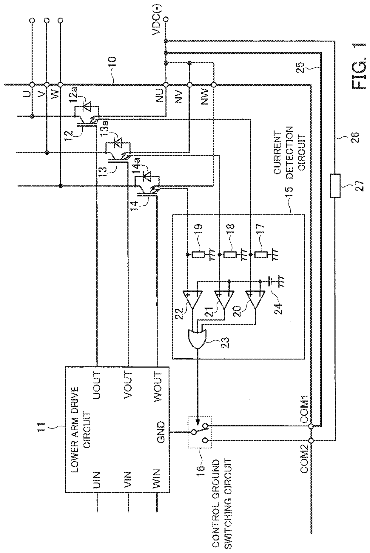
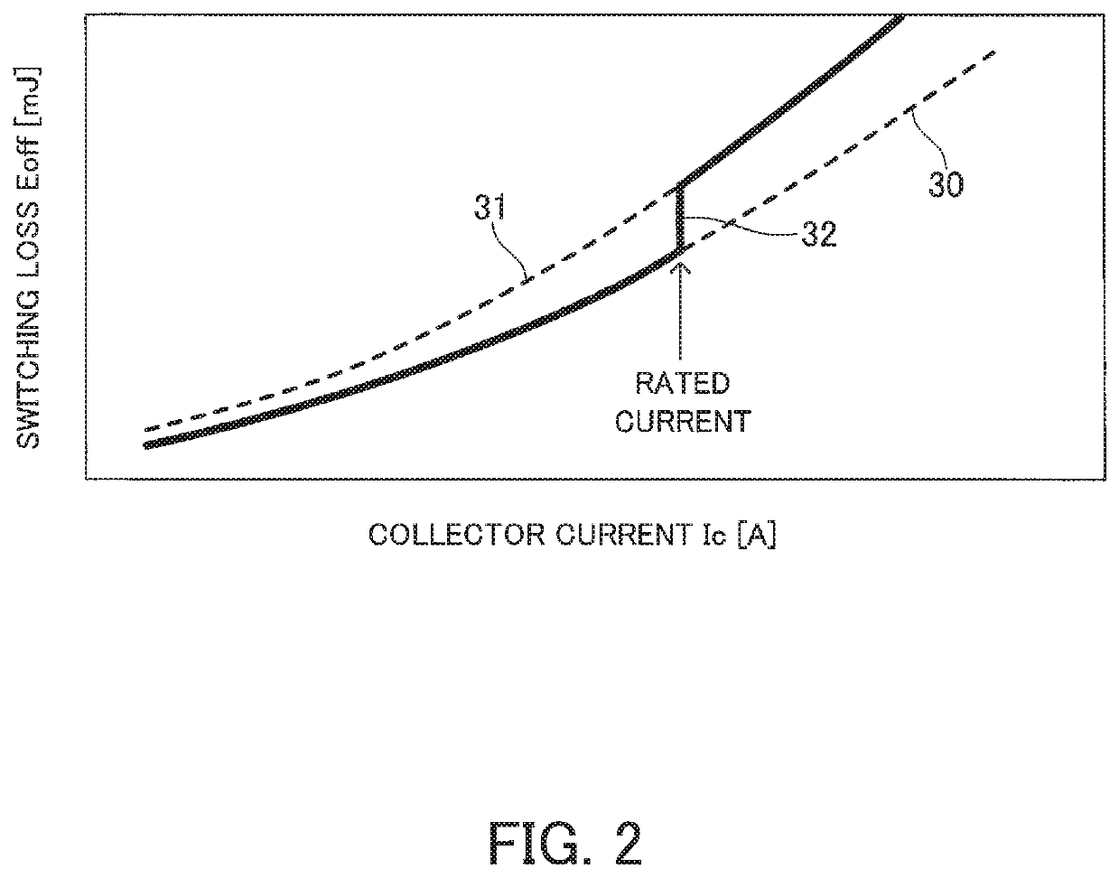
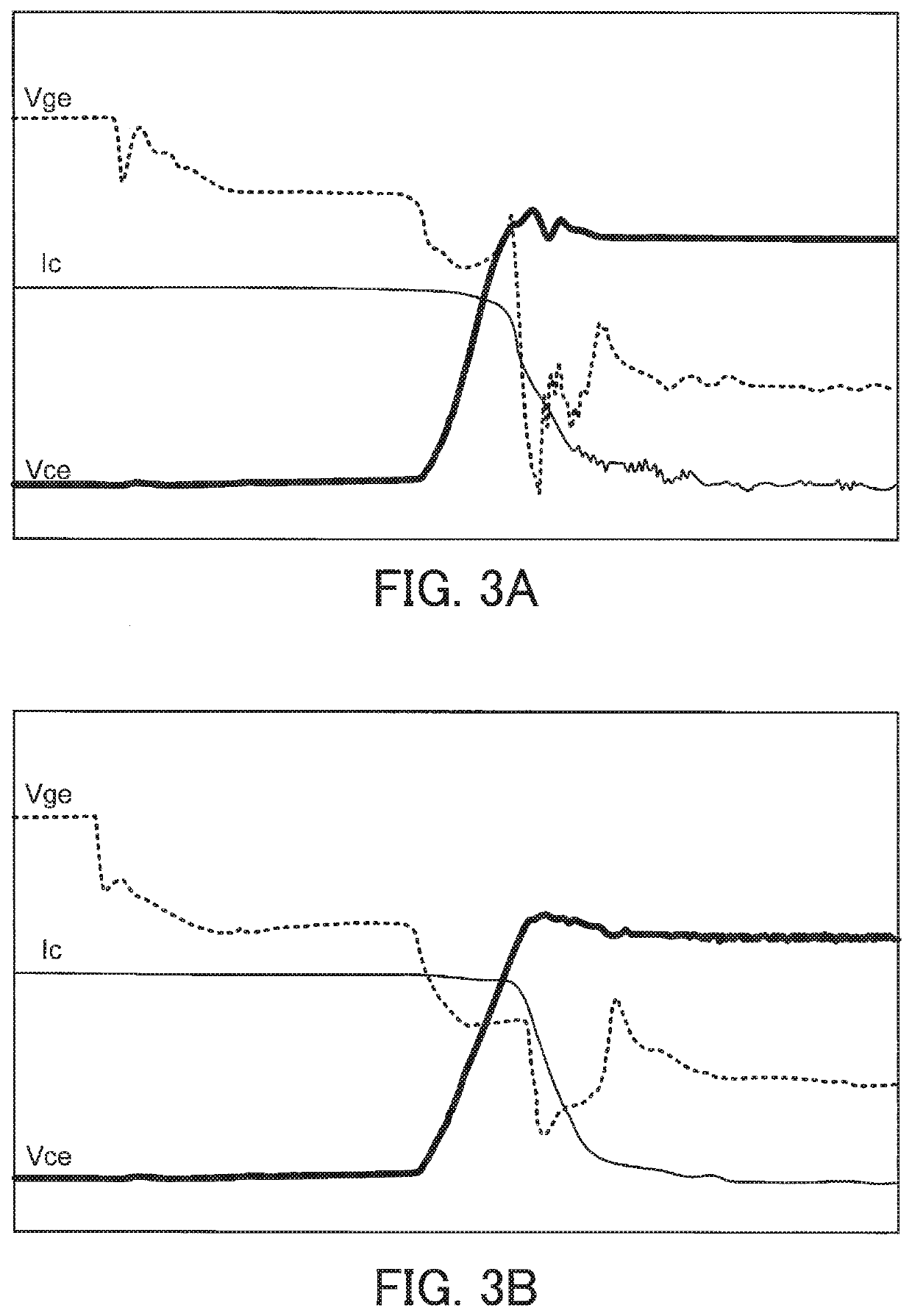
[0037]FIG. 1 is a circuit diagram illustrative of part of an intelligent power module according to a FIG. 2 illustrates a change in switching loss at turn-off time relative to a collector current of a switching element. FIGS. 3A and 3B illustrate switching waveforms obtained when a switching element is turned off. FIG. 3A illustrates switching waveforms obtained in a case where a dumping resistor is not used. FIG. 3B illustrates switching waveforms obtained in a case where a dumping resistor is used.

[0038]An intelligent power module 10 illustrated in FIG. 1 includes a lower arm drive circuit 11, a switching element 12 included in a U-phase lower arm, a switching element 13 included in a V-phase lower arm, and a switching element 14 included in a W-phase lower arm. Furthermore, the intelligent power module 10 includes a current detection circuit 15 and a control ground switching circuit 16. Each of the switching elements 12, 13, and 14 is an IGBT. A freewheeling diode 12a is connect...

second embodiment

[0054]FIG. 4 is a circuit diagram illustrative of part of an intelligent power module according to a Components in FIG. 4 which are the same as or equivalent to those illustrated in FIG. 1 are marked with the same numerals and detailed descriptions of them will be omitted. Furthermore, in order to simplify a figure, only circuits related to the U phase are illustrated in FIG. 4.

[0055]With an intelligent power module 10a according to a second embodiment, not only the driving impedance of a ground wiring of a lower arm drive circuit 11 but also the driving impedance of a corresponding wiring of an upper arm drive circuit are switched according to a current value.

[0056]FIG. 4 illustrates only the circuits related to the U phase. However, the structure of a lower arm in the intelligent power module 10a is the same as that of the lower arm in the intelligent power module 10 illustrated in FIG. 1. Accordingly, a detailed description of a lower arm drive circuit 11 will be omitted. Furthe...


PUM


Abstract

A power module including a half bridge circuit having first and second switching elements respectively included in an upper arm and a lower arm thereof, and upper and lower arm drive circuits which respectively drive the first and second switching elements. The power module includes a first ground terminal on a ground side of the second switching element, a second ground terminal connected, via a first ground wiring, to the first ground terminal, a third ground terminal connected, via a second ground wiring including a dumping resistor, to the first ground terminal, a current detection circuit detecting a current flowing through the second switching element, and a control ground switching circuit which performs switching according to a value of the current detected by the current detection circuit, so as to connect a ground terminal of the lower arm drive circuit to the second or third ground terminal.

Description

CROSS-REFERENCE TO RELATED APPLICATION[0001]This application is a continuation application of International Application PCT / JP2019 / 021745 filed on May 31, 2019 which designated the U.S., which claims priority to Japanese Patent Application No. 2018-134137, filed on Jul. 17, 2018, the entire contents of which are incorporated herein by reference.BACKGROUND OF THE INVENTION1. Field of the Invention[0002]The embodiments discussed herein relate to a power module with a built-in drive circuit.2. Background of the Related Art[0003]With motor drive inverters a power module including a plurality of combinations of a half bridge circuit made up of two switching elements connected in series and a drive circuit which on-off drives the switching elements is used.[0004]FIG. 5 is a circuit diagram illustrative of an example of the structure of a power module used in a three-phase motor drive inverter. FIGS. 6A and 6B illustrate switching waveforms obtained when a lower-arm switching element is tu...

Claims


Application Information

Patent Timeline
Patent Type & Authority Applications(United States)
IPC IPC(8): H02P27/06H02M1/088
CPCH02M1/088H02P27/06H02M1/08H02M1/32H02M7/5387H02M1/0009
Inventor ARAKI, RYU
Owner FUJI ELECTRIC CO LTD
Why Eureka
Try Eureka