Spinal instrumentation to enhance osteogenesis and fusion

a technology of spine and bone, applied in the field of spine fixation and osteogenesis, can solve the problems of poor bone stock, unstable bone, and easy failure of wire electrodes,

Inactive Publication Date: 2020-10-22
OSTEOVANTAGE INC
View PDF0 Cites 0 Cited by
  • Summary
  • Abstract
  • Description
  • Claims
  • Application Information

AI Technical Summary

Benefits of technology

[0012]In some embodiments, the first and second screws have the same anodization pattern. The first and second screws can have different anodization patterns. In some embodiments, the first and second screws are configured to function independent of one another to induce osteogenic effect in tissue directly adjacent to each screw when the screws are energized. In some embodiments, the first and second screws are configured to work in combination to produce a synergistic electric field when the screws are energized. In some embodiments, at least one of the screws comprises an anodization layer positioned at a top portion of the screw.
[0013]The layer can extend over at least a portion of a head and shaft of the screw. In some embodiments, at least one of the screws comprises a selectively anodized surface that extends over about 90% of a total length of the screw. In some embodiments, at least one of the screws comprises a selectively anodized surface that comprises an anodized portion and an unanodized portion. In some embodiments, the anodized portion is configured to prohibit delivery of current to adjacent tissue when the system is implanted. The unanodized portion can be configured to support delivery of current to adjacent tissue when the system is implanted. In some embodiments, at least one of the screws comprises a selectively anodized surface that is configured to selectively direct electrical stimulation to the vertebral body and intervertebral disc space without directing electrical stimulation to the spinal canal. At least one of the screws can comprise a selectively anodized surface that can a single and / or a variable thickness. The variable thickness can be linearly and / or exponentially graded. In some embodiments, at least one of the screws comprises a selectively anodized surface that comprises a first region of a consistent thickness anodization and a second region of a variable thickness anodization. The first region can comprise about 25% a length of the component. The second region can comprise about 75% a length of the component. In some embodiments, at least one of the screws comprises a selectively anodized surface that comprises a segmented coating comprising two or more discontinuous regions of anodization. The first region can be positioned at a top portion of the screw. The second region can be positioned at the bottom portion of the screw. The first region can comprise about 60% a length of the screw. The second region can comprise about 10% a length of the screw. In some embodiments, at least one of the screws comprises an unanodized region comprising about 30% a length of the screw is positioned between the first region and the second region. In some embodiments, a field created in a region distant to the first screw is different from a field created in a region distant to the second screw. The system can further comprise a third selectively anodized pedicle screw configured to be implanted at a third vertebral level, different from the first and second levels, such that the second pedicle screw is positioned between the first and third pedicle screws. In some embodiments, the third screw has a same anodization pattern as the first and second screws. The third screw can have a different anodization pattern as the first and second screws. In some embodiments, the second and third screws are configured to function independent of one another to induce osteogenic effect in tissue directly adjacent to each screw when the screws are energized. In some embodiments, the second and third screws are configured to work in combination to produce a synergistic electric field when the screws are energized.
[0014]In another aspect, a method for inducing osteogenic effect is provided. The method comprises selecting an appropriate anodization pattern for a selectively anodized pedicle screw; implanting a spinal fixation system comprising the selectively anodized pedicle screw; energizing the pedicle screw using a constant level of direct current, thereby producing a desired electrical field in an area proximate to the pedicle screw; and producing an osteogenic effect in surrounding tissue and structures. Energizing the screw can comprise applying a direct current of about 60 μA. The method can comprise connecting the screw to a power source. The method can further comprise implanting a second selectively anodized pedicle screw. The method can further comprise implanting a third selectively anodized pedicle screw.

Problems solved by technology

Although bone growth occurs naturally, it can be stunted or stopped by various factors such as tobacco, alcohol and steroid usage, poor bone stock, and age.
Although these embedded electrodes are generally effective, the wire electrodes are susceptible to failure, requiring additional surgery to repair them.
Moreover, placement of the wire electrodes is less than precise, allowing some of the current to pass through undesirable areas of tissue and encouraging bone to form where it is unneeded.
Imprecise delivery of direct current could also potentially have adverse effects.
Further, imprecise placement may require more energy to be provided to the electrodes than otherwise necessary to be optimally effective.
Thus, there are several drawbacks and potential problems associated with devices such as these.

Method used


Image

  • Spinal instrumentation to enhance osteogenesis and fusion
  • Spinal instrumentation to enhance osteogenesis and fusion
  • Spinal instrumentation to enhance osteogenesis and fusion

Examples


example 1

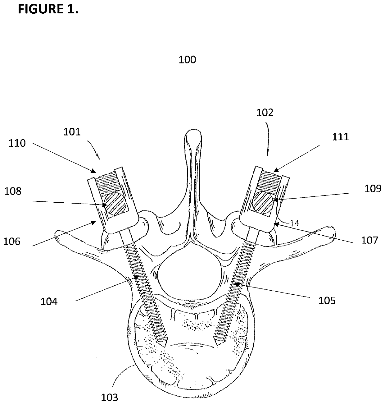
[0073]Instrumented, single-level, posterior lumbar interbody fusion (PLIF) with autologous grant was performed at L4-5 in adult Toggenburg / Alpine goats, using both the spinal systems disclosed herein and standard spinal instrumentation (no electrical stimulation). At terminal time points (3 months, 6 months), animals were killed and lumbar spines were explanted for radiographic analysis using a SOMATOM Dual Source Definition CT Scanner and high-resolution Microcat II CT Scanner. Trabecular continuity, radiodensity, within the fusion mass, and regional bone formation were examined to determine successful spinal fusion.

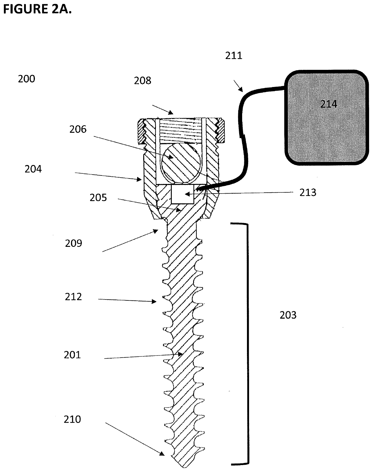
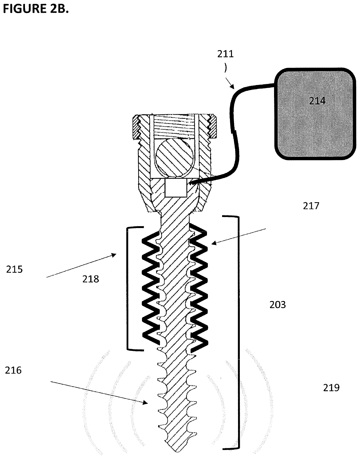
[0074]Osteogenic instrumentation used in the present study consisted of systems described herein configured to focally deliver low-level DC directly into the vertebral bodies including a constant current source, 1 pair of anodized titanium rods, and 2 pairs of selectively anodized pedicle screws. Constant current sources delivering 40 μA DC were a microcircuit board and...

example 2

[0082]COMSOL Multiphysics software V4.3 (COMSOL, Inc., Burlington, Mass.) was utilized to simulate the electric field distribution evoked by electroactive pedicle screws in various tissue compartments and anatomical models of the human spine. Electrostatic, AC / DC, and electric current modules were utilized to model the delivery of various amplitudes of DC current from variably anodized pedicle screws. Resulting linear systems of equations were solved using the conjugate gradients solver and plotted in two and three dimensions. Numerical data was exported to MATLAB (MathWorks, Inc., Natick, Mass.) for further data processing and analysis.

[0083]Model pedicle screws were based on clinical instrumentation commonly utilized in posteriolateral interbody fusion (PLIF) of the human lumbar spine (screw dia.=6.0 mm, screw length=40 mm). Threaded, high-resolution pedicle screw models were created by importing and rending IGES files of human pedicle screws obtained from GrabCAD, Inc. (Boston, M...


PUM


Abstract

Systems and methods for producing osteogenic effect in spinal fixation systems using selectively anodized components are described. Anodization patterns can be selected to produce a desired electric field and osteogenic effect in tissues and structures surrounding the selectively anodized component.

Description

CROSS REFERENCE TO RELATED APPLICATIONS[0001]This application claims the benefit of U.S. Provisional Application No. 62 / 321,092, filed Apr. 11, 2016.INCORPORATION BY REFERENCE[0002]All publications and patent applications mentioned in this specification are incorporated herein by reference in their entirety to the same extent as if each individual publication or patent application was specifically and individually indicated to be incorporated by reference.FIELD[0003]The application relates to the fields of spinal fixation and osteogenesis.BACKGROUND[0004]Bone growth is desirable in many instances, such as when vertebrae in a patient's spine are fused to overcome pain and other effects caused by inter-vertebral movement or intra-vertebral movement. Although bone growth occurs naturally, it can be stunted or stopped by various factors such as tobacco, alcohol and steroid usage, poor bone stock, and age. Moreover, stimulating bone growth to speed recovery is desirable in some instances...

Claims


Application Information

Patent Timeline
Patent Type & Authority Applications(United States)
IPC IPC(8): A61F2/28A61B17/70A61B17/86A61N1/20
CPCA61B17/8625A61B17/7032A61B2017/00734A61N1/205A61F2002/2821A61B2017/564A61F2/28A61B17/7002A61B17/8615A61N1/05A61N1/20A61N1/36A61B17/7004A61B17/8605A61N1/326A61B17/863A61B17/866
Inventor MACEWAN, MATTHEW R.LEUTHARDT, ERIC C.MORAN, DANIEL W.
Owner OSTEOVANTAGE INC
Why Eureka
Try Eureka