Electronic device

Pending Publication Date: 2020-10-22
MURATA MFG CO LTD
View PDF0 Cites 0 Cited by
  • Summary
  • Abstract
  • Description
  • Claims
  • Application Information

AI Technical Summary

Benefits of technology

[0009]According to the electronic device of the exemplary embodiment, the peripheral edge portion of the upper exterior body made of the material having waterproof properties and the peripheral edge portion of the lower exterior body are made in close contact with each other. Moreover, the wiring substrate on which the operation switch and the electronic component are mounted is housed therein (e.g., in a sealed space formed by the upper exterior body and the lower exterior body), so that waterproof properties are provided with a relatively simple structure. On the other hand, the lining member is disposed on a back surface of the upper exterior body, and the buffer member is disposed between the wiring substrate and the lining member, so that a shape of the upper exterior body can be held and deformation can be suppressed. In addition, when the operation switch is operated, the lining member bends in the operation direction (for example, a pressing direction) of the operation switch to receive the pressing force caused by the switch operation of a user and the buffer member is compressively deformed. Therefore, the pressing force associated with the switch operation by the user can be absorbed. As such, the stress applie

Problems solved by technology

Therefore, when stress is applied to the electronic components and the like and the stress is repeated, failure

Method used


Image

  • Electronic device
  • Electronic device
  • Electronic device

Examples


Example

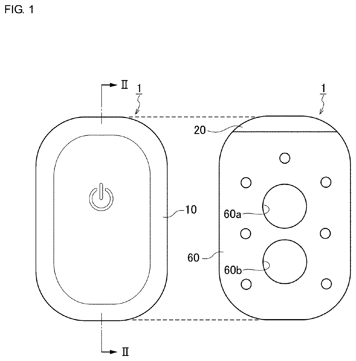
[0020]Hereinafter, exemplary embodiments of the present invention will be described in detail with reference to the accompanying drawings. It is noted that in the drawings, the same or corresponding parts will be denoted by using the same reference numerals. Further, in each drawing, the same elements are denoted by the same reference numerals, and redundant description thereof will be omitted. Note that, here, a non-heating type core body thermometer (hereinafter simply referred to as “core body thermometer”) will be described as an example of an electronic device according to the present invention.

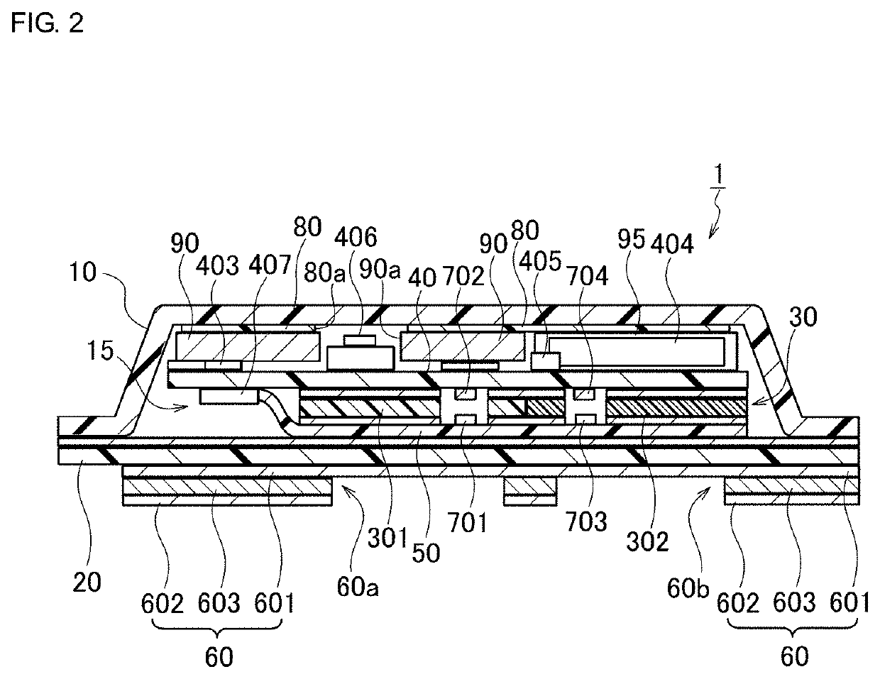
[0021]First, a configuration of a core body thermometer 1 according to the exemplary embodiment will be described with reference to FIG. 1 to FIG. 7. FIG. 1 includes a plan view and a bottom view illustrating an appearance of the core body thermometer 1. FIG. 2 is a cross-sectional view illustrating the configuration of the core body thermometer 1 (cross-sectional view taken along a line...


PUM


Abstract

A core body thermometer that includes a wiring substrate on which a power supply switch and electronic components are mounted. The power supply switch is housed so as to face a back surface of an upper exterior body in a space formed by the upper exterior body and a lower exterior body. Moreover, a lining member is formed in a thin plate shape and disposed on the back surface of the upper exterior body, and a buffer member is disposed between the wiring substrate and the lining member. The lining member has a through-hole in which the power supply switch is placed in an inner side in a thickness direction when viewed in a plan view, and has flexibility in an operation direction of the power supply switch).

Description

CROSS REFERENCE TO RELATED APPLICATIONS[0001]The present application is a continuation of PCT / JP2019 / 000646 filed Jan. 11, 2019, which claims priority to Japanese Patent Application No. 2018-003130, filed Jan. 12, 2018, the entire contents of each of which are incorporated herein by reference.TECHNICAL FIELD[0002]The present invention relates to an electronic device, and more particularly, to an electronic device having waterproof properties.BACKGROUND[0003]Depending on the application, waterproof properties may be required for an electronic device. In the electronic device being required such waterproof properties, the waterproof properties are required also for an operation switch for receiving a user operation. For example, Patent Document 1 (identified below) discloses an electronic device with a button operable in water.[0004]More specifically, the electronic device in Patent Document 1 includes a substrate main body having a first surface and a second surface that face away fr...

Claims


Application Information

Patent Timeline
IPC IPC(8): G01K7/22H05K1/18H05K7/14G01K1/14G01K1/02
CPCG01K1/14G01K1/024H05K2201/10053H05K7/1427G01K7/22H05K1/181G01K2215/00A61B5/01G01K1/08H01H9/04H01H13/06G01K1/16G01K13/25G01K13/20
Inventor SHIMUTA, TORU
Owner MURATA MFG CO LTD
Why Eureka
Try Eureka