Wearable devices

a head-up display and wearable technology, applied in the field of wearable head-up displays, can solve the problems of inconvenient non-military applications, and even for certain military applications

Active Publication Date: 2020-10-29
SNAP INC
View PDF0 Cites 4 Cited by
  • Summary
  • Abstract
  • Description
  • Claims
  • Application Information

AI Technical Summary

Benefits of technology

[0008]Optionally, the frame may be hingeably attached to the arm at a location between the collimation optic and the combiner assembly. Advantageously, this allows for convenient folding of the display and therefore easy storage and portability.
[0017]Optionally, the arm may be arranged to fold in a plane through the optical axis of the image projection means. Advantageously, this allows for convenient folding of the display and therefore easy storage and portability.

Problems solved by technology

Military applications of wearable head up displays have utilised the visor of a helmet as the transparent component, but this is in inconvenient for non-military applications, and even for certain military applications.

Method used


Image

  • Wearable devices
  • Wearable devices
  • Wearable devices

Examples


Embodiment Construction

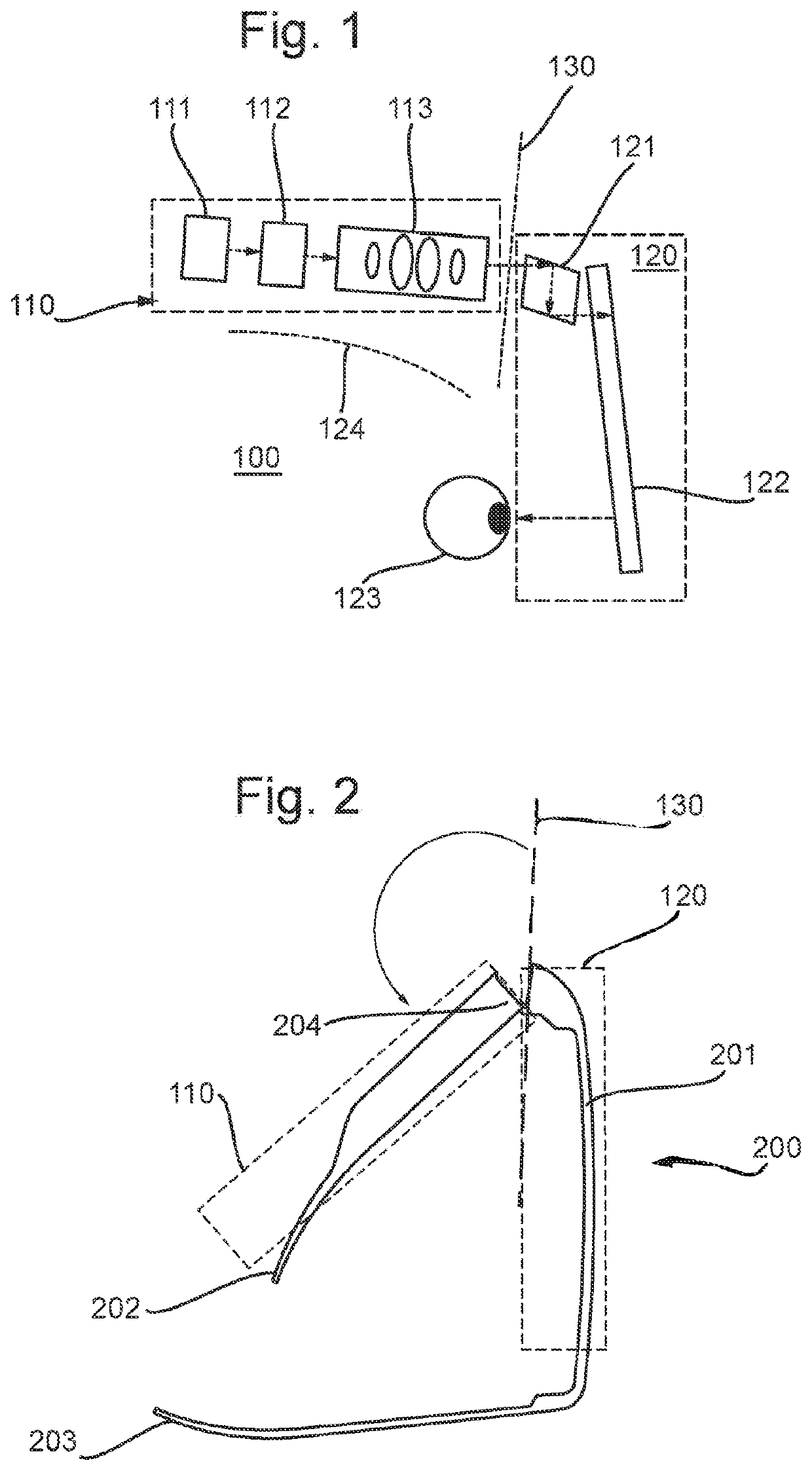
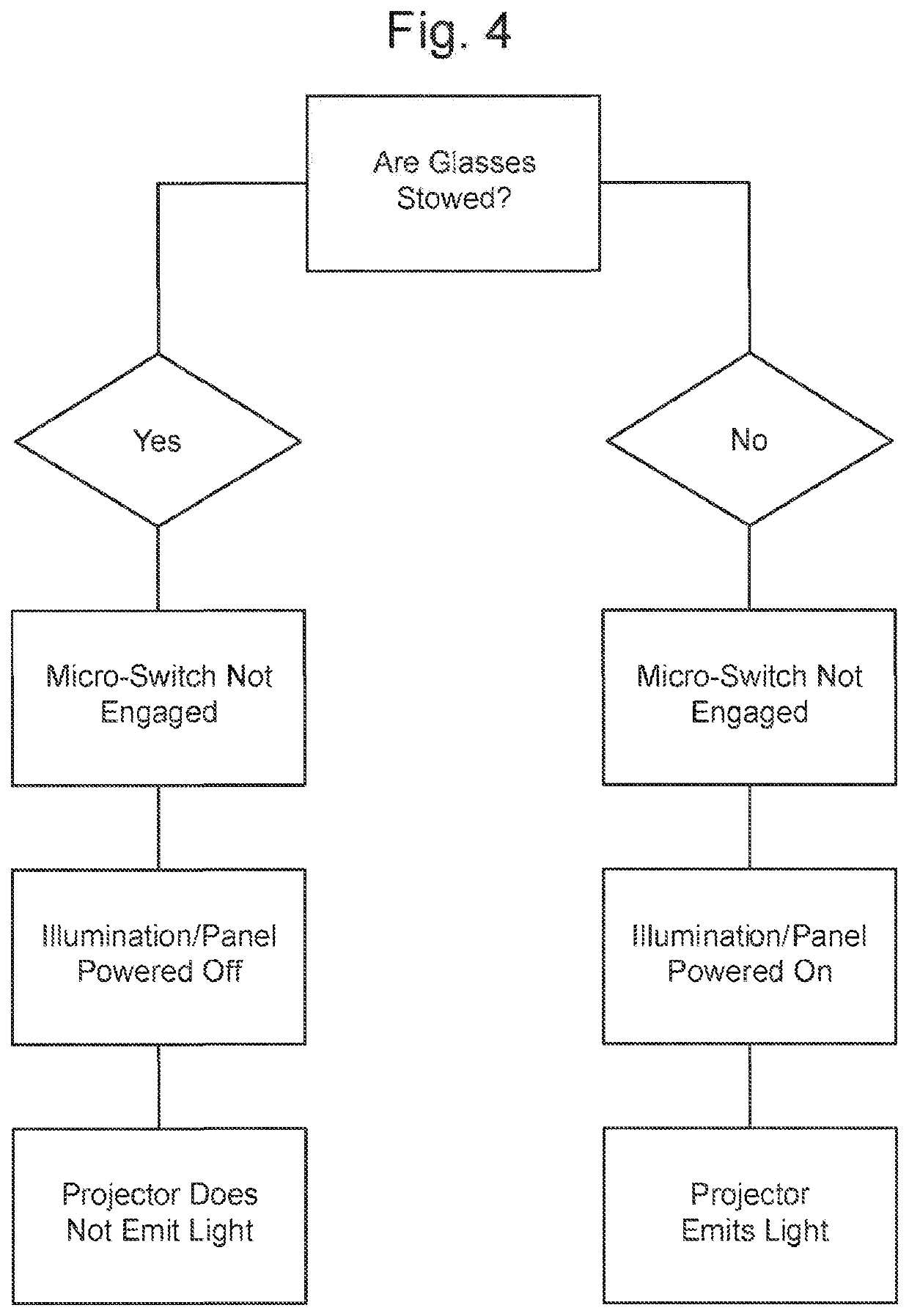
[0023]A head-up display utilizes an optical projection device to project light containing image content into or onto a transparent component, which then directs the light to the user's eye in the required location. Typically, the projection device comprises a light source such as an LED or laser diode, an imaging device such as a DMD, LCD, LCoS or OLED panel, and collimation optics to project the light into or onto the transparent component. To achieve the required brightness and optical quality, these components are of substantial size. For a wearable head-up display instance, these components are integrated into an assembly intended to be worn by a user.

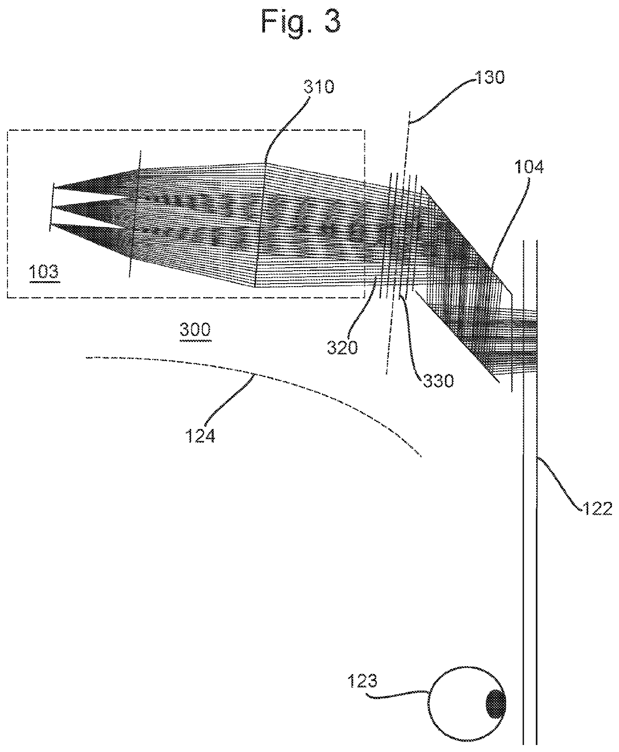
[0024]In order to provide suitable positioning and stability of the optical source and collimation optics, these parts have conventionally been formed in a rigid structure with the transparent component, orientated about the head and face of a user. This ensures comfortable mounting and provides rigidity to ensure correct optical a...


PUM


Abstract

A wearable head-up display which allows for convenient and safe stowage when not in use. A hinge component is positioned within the optical path from an image projector to a display component which ensures optical alignment for projection. A detection means is provided to signal when the wearable device is in a folded position in order to deactivate the projector.

Description

FIELD OF THE INVENTION[0001]The present disclosure relates to wearable head-up displays.BACKGROUND ART[0002]Head-up displays overlay a projected image on to a person's view of the real-world, such that they perceive both the real-word image and the projected image. Head-up displays utilise a transparent component through which the user looks and which projects the image such that it appears in the user's vision.[0003]The transparent component may be a fixed component, such as a clear screen in an aircraft, or may be worn by a user. Military applications of wearable head up displays have utilised the visor of a helmet as the transparent component, but this is in inconvenient for non-military applications, and even for certain military applications. Devices with much smaller transparent components, which are worn like spectacles, have been provided, but are still large enough devices such that the optical projection components, such as the light source and optics, prevent folding of t...

Claims


Application Information

Patent Timeline
Patent Type & Authority Applications(United States)
IPC IPC(8): G02B27/01G02C5/22
CPCG02B27/0176G02B27/0172G02C5/22G02B2027/0167G02B2027/015G02B2027/0178G02C5/2272G02B27/017G02B2027/0156G02B2027/014
Inventor MILLS, RORY THOMAS ALEXANDERHARRIS, SAMUEL WILLIAM
Owner SNAP INC
Why Eureka
Try Eureka