Inductor, Device Equipped with Inductor and Method for Manufacturing Inductor

US20200343036A1Pending Publication Date: 2020-10-29INST OF NAT COLLEGES OF TECH JAPAN +1

Image

  • Inductor, Device Equipped with Inductor and Method for Manufacturing Inductor
  • Inductor, Device Equipped with Inductor and Method for Manufacturing Inductor
  • Inductor, Device Equipped with Inductor and Method for Manufacturing Inductor

Examples


Embodiment Construction

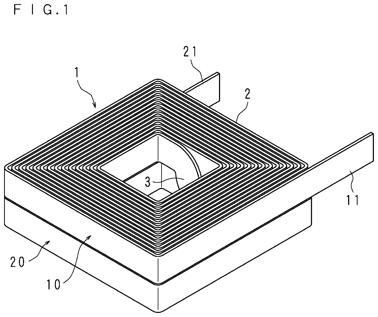
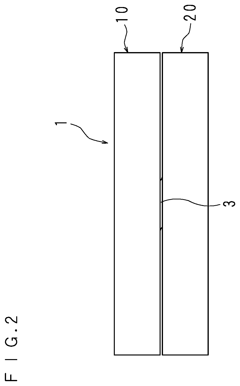
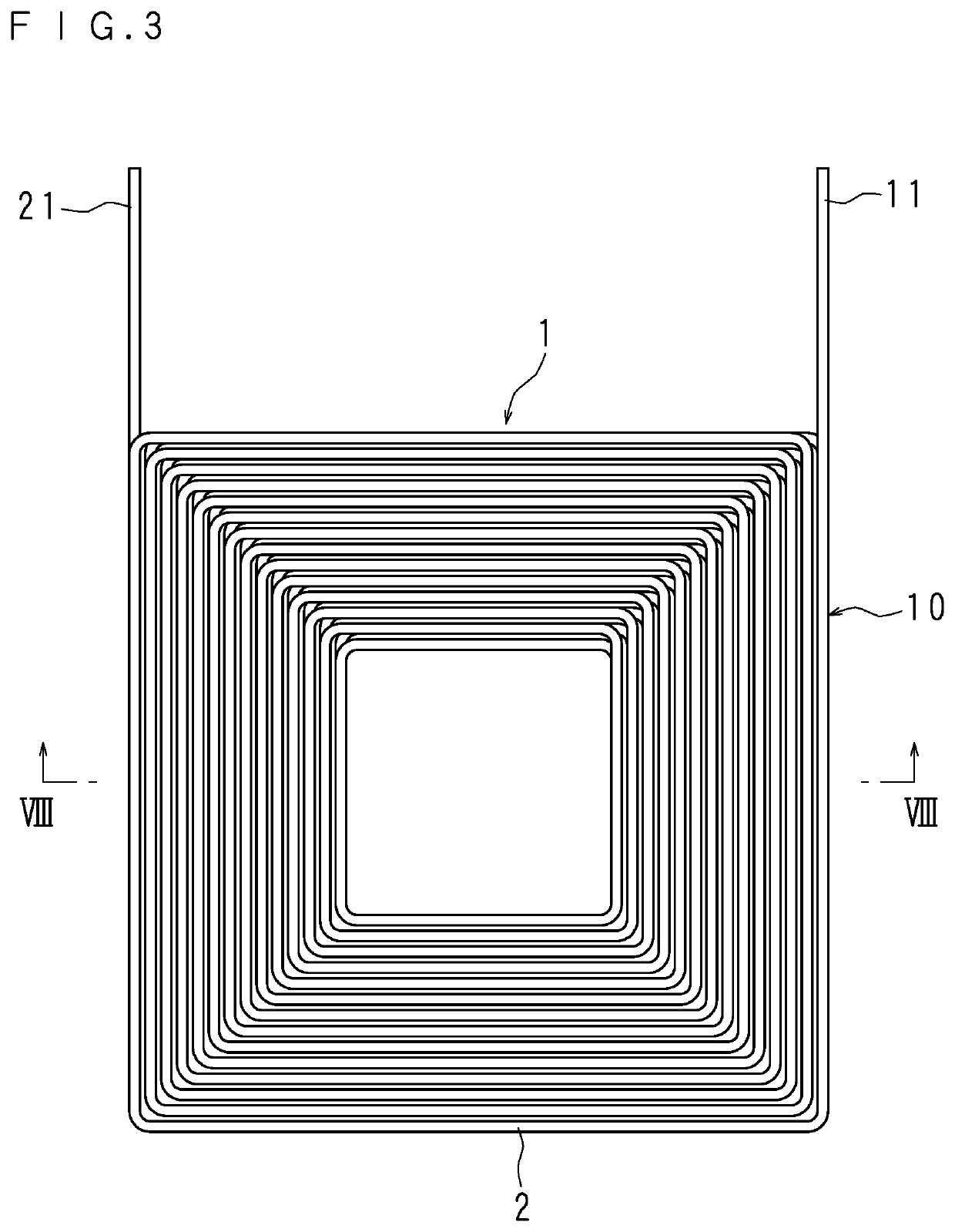
[0042]An inductor 1 according to an embodiment of the present invention will be described below with reference to drawings. FIG. 1 is a perspective view schematically illustrating the inductor 1, FIG. 2 is an elevation view schematically illustrating the inductor 1, FIG. 3 is a plan view schematically illustrating the inductor 1, FIG. 4 is a right-side view schematically illustrating the inductor 1, FIG. 5 is a left-side view schematically illustrating the inductor 1, FIG. 6 is a rear view schematically illustrating the inductor 1, and FIG. 7 is a bottom view schematically illustrating the inductor 1.

[0043]The inductor 1 includes a first coil part 10 and a second coil part 20 that are axially aligned. The first coil part 10 and the second coil part 20 are formed by alpha-winding and connected to each other. Each of the first coil part 10 and the second coil part 20 is formed by flatwise-winding a flat wire 2, and is quadrilateral, for example, square or rectangular when viewed from ...


PUM


Abstract

An example inductor comprises multiple coil parts and each formed by flatwise-winding layers of turns of a flat wire arranged in a radial direction with gaps between each of the layers, and the multiple coil parts are arranged in an axial direction with a clearance. There is provided a clearance between the multiple coil parts, through which air flows, achieving improvement in heat dissipation.

Description

CROSS-REFERENCE TO RELATED APPLICATIONS[0001]This application is the national phase under 35 U.S.C. § 371 of PCT International Application No. PCT / JP2019 / 001264 which has International filing date of Jan. 17, 2019 and designated the United States of America.FIELD[0002]The technology herein relates to an inductor, a device equipped with the inductor and a method of manufacturing the inductor.BACKGROUND AND SUMMARY[0003]An inductor with a coil formed by flatwise-winding a flat wire has been conventionally proposed. A flat wire, which can be tightly wound and can thus achieve a higher density compared to a round wire, has an advantage of increasing the self inductance of the coil.[0004]As an inductor with such a structure, an inductor with a single layer annular coil formed by flatwise-winding a flat wire onto a core has been previously proposed.[0005]The use of a core produces an effect of increasing the self inductance of the coil as compared with an air-core case in addition to the ...

Claims


Application Information

Patent Timeline
29 Oct 2020
Publication
US20200343036A1
IPC
H01F27/28; H03H7/40; H01F41/061
CPC
H03H7/40; H01F41/061; H01F27/2823; H01F17/02; H03H7/38; H01F27/2847; H01F27/006; H01F27/2876
Inventors
NAKAHAMA, MASAYUKI; MAEDA, KOSUKE