RF electrostatic chuck filter circuit

a filter circuit and electrostatic chuck technology, applied in the field of semiconductor processing, can solve the problems of power loss, damage to the power supply of the chucking electrode, and capacitive coupling

Active Publication Date: 2020-10-29
APPLIED MATERIALS INC
View PDF0 Cites 4 Cited by
  • Summary
  • Abstract
  • Description
  • Claims
  • Application Information

AI Technical Summary

Problems solved by technology

However, when RF power is used, capacitive coupling can occur between the plasma and a chucking electrode in an electrostatic chuck.
The capacitive coupling results in RF coupling which induces high RF voltage and current on and through the chucking electrode which results in loss of power and damage to a power supply of the chucking electrode.

Method used


Image

  • RF electrostatic chuck filter circuit
  • RF electrostatic chuck filter circuit
  • RF electrostatic chuck filter circuit

Examples


Embodiment Construction

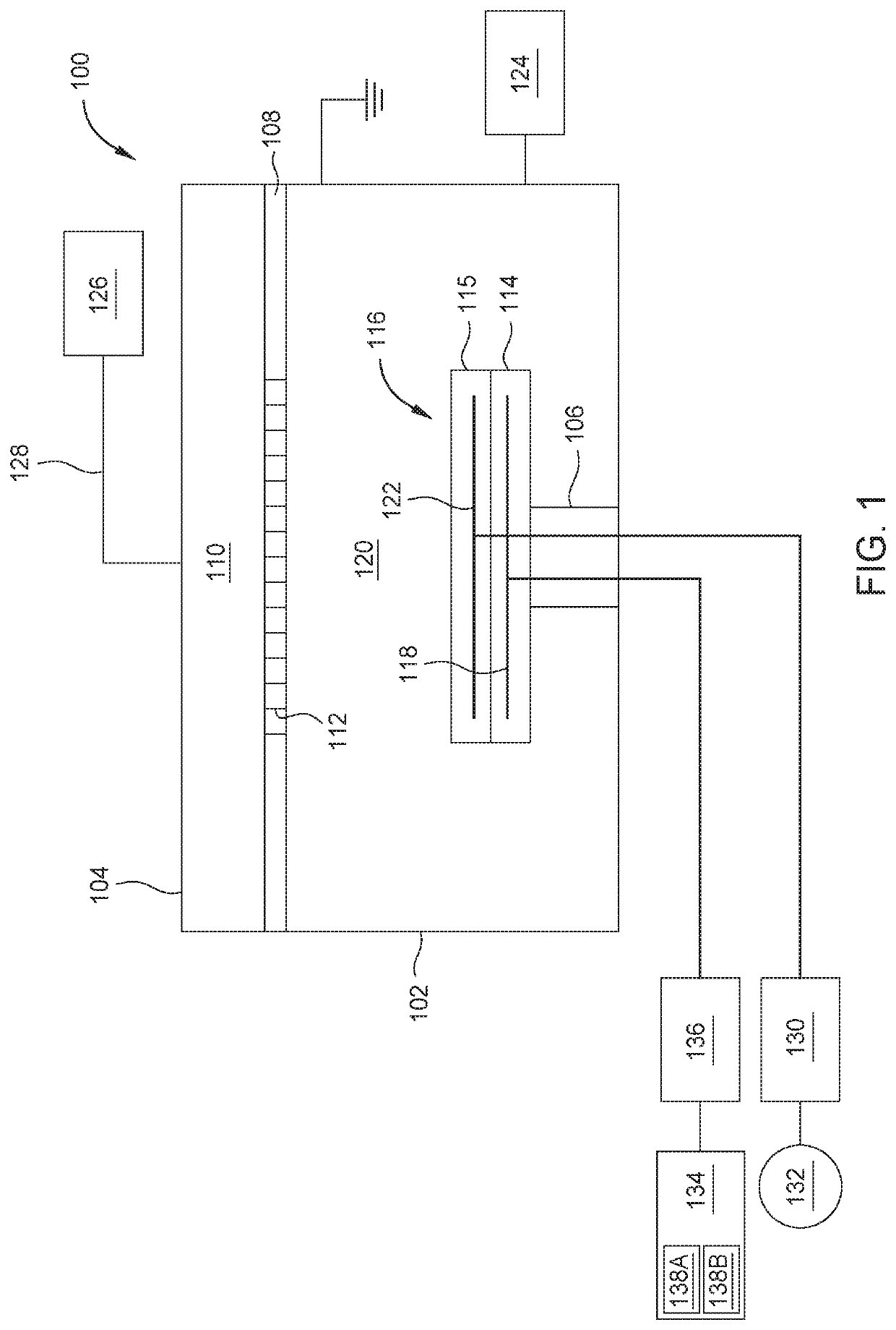
[0016]Embodiments described herein relate to apparatus and methods for substantially reducing an occurrence of radio frequency (RF) coupling through a chucking electrode. The chucking electrode is disposed in a substrate support that is coupled to a process chamber body. An RF source is used to generate a plasma in a process volume adjacent to the substrate support. An impedance matching circuit is disposed between the RF source and a chucking electrode disposed in the substrate support. To reduce an occurrence of damage to the chucking electrode and a chucking power source coupled thereto, an electrostatic chuck filter is coupled between the chucking electrode and the chucking power source.

[0017]FIG. 1 is a schematic view of a process chamber 100 according to one embodiment. The process chamber 100 includes a chamber body 102 and a lid 104 defining a process volume 120 therein. A substrate support 114 and a gas distribution plate 108 are disposed in the process volume 120. The subs...


PUM

PropertyMeasurementUnit
frequencyaaaaaaaaaa
frequencyaaaaaaaaaa
impedanceaaaaaaaaaa

Abstract

Embodiments described herein relate to apparatus and methods for substantially reducing an occurrence of radio frequency (RF) coupling through a chucking electrode. The chucking electrode is disposed in an electrostatic chuck positioned on a substrate support. The substrate support is coupled to a process chamber body. An RF source is used to generate a plasma in a process volume adjacent to the substrate support. An impedance matching circuit is disposed between the RF source and the chucking electrode is disposed in the electrostatic chuck. An electrostatic chuck filter is coupled between the chucking electrode and the chucking power source.

Description

CROSS-REFERENCE TO RELATED APPLICATIONS[0001]This application claims priority to U.S. Provisional Patent Application No. 62 / 839,301, filed Apr. 26, 2019, which is hereby incorporated by reference in its entirety.BACKGROUNDField[0002]Embodiments of the present disclosure generally relate to semiconductor processing, and more specifically to apparatus and methods to generate and control radio frequency plasma for thin film deposition.Description of the Related Art[0003]In the fabrication of integrated circuits, deposition processes, such as chemical vapor deposition (CVD), are often used to deposit films of various materials on substrates. In plasma-enhanced chemical vapor deposition (PECVD), for instance, electromagnetic energy is applied to at least one precursor gas or vapor to generate a plasma.[0004]In some examples, the electromagnetic energy used to generate the plasma can be radio frequency (RF) power. However, when RF power is used, capacitive coupling can occur between the p...

Claims


Application Information

Patent Timeline
Patent Type & Authority Applications(United States)
IPC IPC(8): H01L21/683H01J37/32
CPCH01L21/6833H01J37/32183H01J37/32091H01L21/6831H01J37/32174H01J37/32532H01J37/3244C23C14/34
Inventor YE, ZHENG JOHNHAYWOOD, EDWARDFISCHBACH, ADAMFRANKLIN, TIMOTHY JOSEPH
Owner APPLIED MATERIALS INC
Why Eureka
Try Eureka