
Photovoltaic inverter system and method for controlling the same

a photovoltaic inverter and inverter technology, applied in photovoltaic energy generation, power conversion systems, ac network circuit arrangements, etc., can solve the problems of high voltage and high energy, reliability problems or economic losses, cost increase, etc., to achieve simple structure, easy control and debugging, and high reliability

Active Publication Date: 2020-10-29
DELTA ELECTRONICS SHANGHAI CO LTD
View PDF0 Cites 2 Cited by
  • Summary
  • Abstract
  • Description
  • Claims
  • Application Information

AI Technical Summary

Benefits of technology

The invention is an optimizing module for a photovoltaic inverter system that can control the system's operating state without traditional communication with the inverter. It has a simple structure, high reliability, ease of controlling, and complete function. It can appropriately control the output voltage to ensure safe start-up of the inverter and have a Rapid Shut-Down (RSD) function. This makes it easier to operate and control the inverter system.

Problems solved by technology

On the other hand, the photovoltaic panels connected in series and in parallel may have high voltage and high energy, and when an emergency (earthquake, fire, etc.) occurs, these photovoltaic panels with high voltage and high energy have to be immediately shut down to prevent any further damage caused by these panels with high voltage and high energy.
However, the optimizers on the roof need to communicate with an inverter of subsequent power stage to achieve rapid shut-down, for example, by adding a modem circuit, such that the cost is increased and the transmitted data is vulnerable to the interference of energy signals and the like, the communication also create reliability problem or economic loss due to poor communication or interference.

Method used


Image

  • Photovoltaic inverter system and method for controlling the same
  • Photovoltaic inverter system and method for controlling the same
  • Photovoltaic inverter system and method for controlling the same

Examples


first embodiment

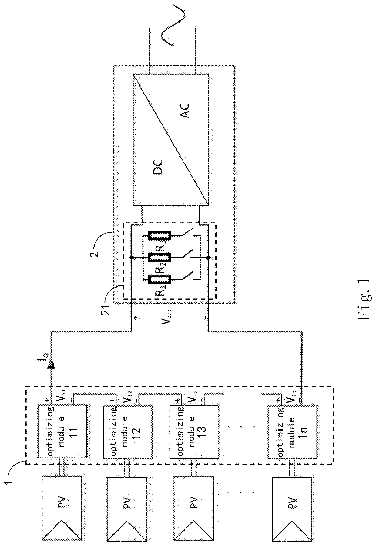
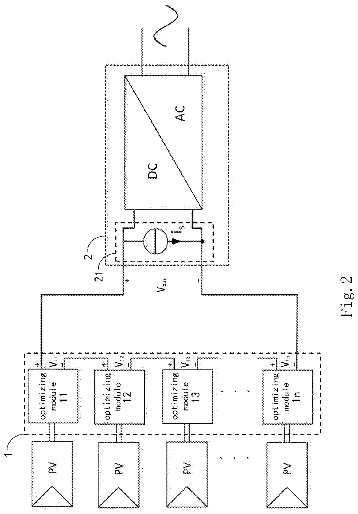
[0048]FIG. 1 is a diagram showing a structure of a photovoltaic inverter system according to the invention. As shown in FIG. 1, the photovoltaic inverter system of the invention comprises: an optimizing module string 1 and an inverter 2. The optimizing module string 1 comprises a plurality of optimizing modules 11, . . . , 1n, each having an input port coupled to at least one photovoltaic module, such as PV panel, wherein n is a positive integer. The output ports of the plurality of optimizing modules 11, . . . , 1n are connected in series. Each of the optimizing modules 11, . . . , 1n comprises a control unit. An input port of the inverter 2 is coupled to an output port of the optimizing module string 1. The inverter 2 comprises an auxiliary detection module 21 connected in parallel with the input port of the inverter 2 for detecting an output current of the optimizing module string 1. The control unit controls an output voltage of the optimizing module string 1 based on the output...

second embodiment

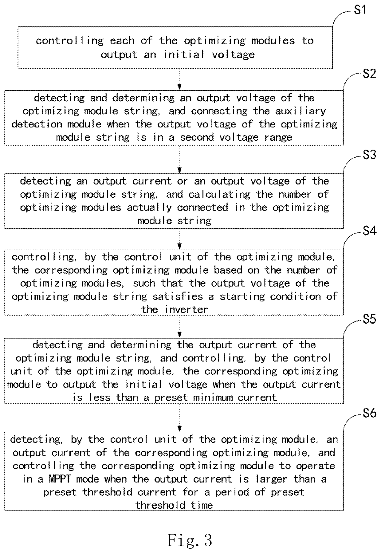
[0070]FIG. 7 is a flow diagram showing the step S3 in the control method according to the invention. The steps of the control method shown in FIG. 7 are substantially the same as the steps of the control method shown in FIGS. 3-6, and the same parts will not be explained in detail.

[0071]As shown in FIG. 7, the step S3 comprises:

[0072]step S31′ for detecting, by the inverter, the output voltage Vbus of the optimizing module string, and calculating the number N of optimizing modules actually connected in the optimizing module string; it shall be noted that the preset voltage Vset of each optimizing module is stored inside the inverter in advance, and the number N of optimizing modules actually connected is calculated by the inverter based on the formula N=Vbus / Vset;

[0073]step S32′ for switching the auxiliary detection module on and off to transmit pulses to the optimizing module string, wherein the number of pulses is proportional to the number of optimizing modules. In one embodiment...


PUM


Abstract

The invention discloses a photovoltaic inverter system and a method for controlling the same. The photovoltaic inverter system comprises: an optimizing module string and an inverter, wherein the optimizing module string comprises a plurality of optimizing modules each having an input port coupled to at least one photovoltaic module, output ports of the plurality of optimizing modules are connected in series, each of the optimizing modules comprises a control unit, an input port of the inverter is coupled to an output port of the optimizing module string, the inverter comprises an auxiliary detection module for auxiliary detecting an output current of the optimizing module string, and the control unit controls an output voltage of the optimizing module string based on the output current of the optimizing module string, such that the output voltage satisfies a start-up condition of the inverter.

Description

CROSS-REFERENCE TO RELATED APPLICATIONS[0001]This non-provisional application claims priority under 35 U.S.C. § 119(a) on Patent Application No. 201910329041.8 filed in P.R. China on Apr. 23, 2019, the entire contents of which are hereby incorporated by reference.[0002]Some references, if any, which may include patents, patent applications and various publications, may be cited and discussed in the description of this invention. The citation and / or discussion of such references, if any, is provided merely to clarify the description of the present invention and is not an admission that any such reference is “prior art” to the invention described herein. All references listed, cited and / or discussed in this specification are incorporated herein by reference in their entireties and to the same extent as if each reference was individually incorporated by reference.TECHNICAL FIELD[0003]The invention relates to a photovoltaic inverter system and a method for controlling the same, and part...

Claims


Application Information

Patent Timeline
Patent Type & Authority Applications(United States)
IPC IPC(8): H02J3/38H02S40/32
CPCH02J3/385H02S40/32H02J3/381H02J2300/26Y02E10/56H02M1/36H02M1/007H02M1/0077H02J3/388
Inventor ZHU, XUANCAIWENG, BINGWENWANG, QINZHAO, WEI
Owner DELTA ELECTRONICS SHANGHAI CO LTD
Learn More