Tobacco evaporator and heating control method

a technology of evaporator and heating wire, which is applied in tobacco, tobacco smoke filter, food science, etc., can solve the problems of affecting the consistency of a heating rate of the product, irritating the taste of baked smoke, and affecting the heat dissipation of the second chamber, so as to shorten the preheating time of the heating wire, reduce the effect of heat dissipation and slowed down second chamber heat dissipation

Active Publication Date: 2020-11-05
SHENZHEN JIANAN TECH CO LTD
View PDF0 Cites 5 Cited by
  • Summary
  • Abstract
  • Description
  • Claims
  • Application Information

AI Technical Summary

Benefits of technology

[0045]One or more technical solutions provided in embodiments of the present application have at least following technical effects or advantages: dispersing heat generated by the heating element by providing mesh filter layer structures, so as to uniformly heat the substance to be evaporated which is placed on the mesh filter layer structures, then scorching will not occur; a heat insulation structure is defined outside the second chamber, when the heating element generates heat, heat dissipation of the second chamber is slowed down, so as to shorten the preheating time of a heating wire and save battery power. The present application effectively solves the technical problem that the tobacco evaporator in the prior art cannot ensure short preheating time and small energy consumption, and cannot achieve softly baking taste and uniform baking smoke.

Problems solved by technology

Therefore, in this method, although the insulation is realized, the heat conduction efficiency is also weakened; the first method also has the problem of affecting the consistency of a heating rate of the product, due to the difference in tightness of the electric-thermal film.
However, the first method and the second method are both directly thermal conduction methods, baked tobacco has a problem of uneven heating, and the taste of baked smoke is irritating.
However, the products of the air heating technology have disadvantages of too long preheating time and too much energy loss.
That is to say, the existing tobacco evaporator cannot solve the technical problem of short preheating time and low energy consumption while softly tasted and uniformly baked smoke.

Method used


Image

  • Tobacco evaporator and heating control method
  • Tobacco evaporator and heating control method
  • Tobacco evaporator and heating control method

Examples


first embodiment

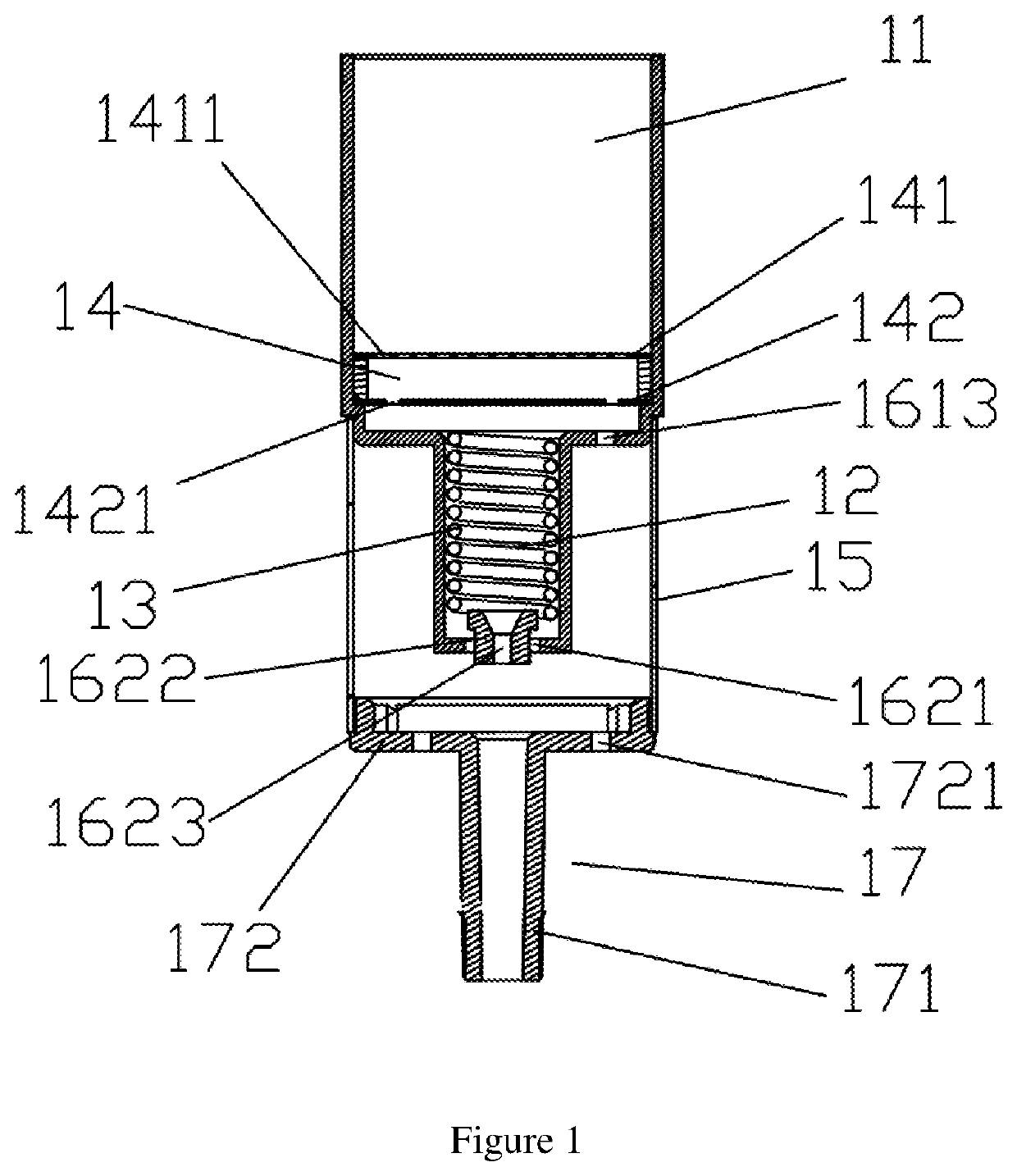
[0058]As shown in FIG. 1, the embodiment of the present application provides a tobacco evaporator comprising a first chamber 11 configured to accommodate a substance to be evaporated, and a second chamber 12 configured to define a heating element 13, the first chamber 11 and the second chamber 12 are communicated with each other to form a first airflow passage; the substance to be evaporated may be cigarette, tobacco, herbs or volatile drugs, etc.

[0059]Referring to FIG. 1, at least two spaced layers of mesh filter layer structures 14 are defined in one end of the first chamber 11 adjacent to the second chamber 12, the filter layer structures 14 comprising a first filter layer 141, and a second filter layer 142 which is defined between the first filter layer 141 and the second chamber 12, the first filter layer 141 is distributed with a plurality of first filter holes 1411, and the second filter layer 142 is provided with a plurality of second filter holes 1421; After cold air enters...

second embodiment

[0074]As shown in FIG. 8, the present application further provides a heating control method comprising following steps

[0075]S1. placing the substance to be evaporated on the first filter layer 141 in the first chamber 11;

[0076]Specifically, the tobacco to be evaporated may be placed in the first chamber 1. The tobacco may be in the form of a strip defined in an axial direction, or may be alternately stacked in different directions, so that the flow gap in the middle of the tobacco layer is larger, the heating is more uniform and can effectively shorten the heating time.

[0077]S2. controlling the heating element 13 to heat cold air entering the first chamber 11 and heating the substance to be evaporated according to the predetermined temperature.

third embodiment

[0078]The step S2 comprises following steps:

[0079]S21, when the airflow sensor 5 detects the airflow signal and transmits to the controller 6, or when the controller 6 is manually controlled to operate by a user, the controller 6 controls the heating element 13 to heat to a first predetermined temperature;

[0080]Specifically, the user controls the controller 6 to start operation through the switch 7, and a temperature adjustment button may also be defined at the switch 7, so that the user can manually set the first predetermined temperature of the heating element 13, in the embodiment, the first predetermined temperature is 200° C. In other embodiments, the first predetermined temperature may be from 80° C. to 300° C.

[0081]S22, the airflow sensor 5 continues detecting the airflow signal, proceeds to step S23; the airflow sensor 5 does not detect the airflow signal again, proceeds to step S24;

[0082]S23. the controller 6 controls the heating element 13 to be heated to a second predeter...


PUM


Abstract

The present application refers to a tobacco evaporator and a heating control method comprising a housing and a suction nozzle connected to the housing; a first chamber and a second chamber which are defined inside the housing, a heating element is defined in the second chamber; a mesh filter layer structure is defined between the first chamber and the heating element to position a substance to be evaporated, and uniformly heat the substance to be evaporated when the heating element generates heat; a thermal insulation structure is defined outside the second chamber to thermally insulate the second chamber while the heating element generates heat. The present application realizes technical effects that the tobacco evaporator has short preheating time, small battery energy consumption, and can bake softly tasted and uniformly baked smoke.

Description

FIELD OF THE PRESENT APPLICATION[0001]The present application relates to a field of electronic cigarette devices, and more particularly relates to a tobacco evaporator and a heating control method.BACKGROUND OF THE PRESENT APPLICATION[0002]At present, there are three methods for a tobacco evaporator to heat substances to be evaporated (such as tobacco, cigarettes, etc.): The first method is that the tobacco pot is made of a thermal conductive material, and a metal heating plate is wrapped around an outer wall of the tobacco pot and transfers heat to the tobacco in the tobacco pot through thermal conduction, so as to achieve the purpose of evaporating an active ingredient of the tobacco; The second method is that the tobacco pot is made of a ceramic material, and a conductive film is printed on an inner portion or an inner wall of a ceramic pot, and the heat generated after energization is conducted to the tobacco through the ceramic pot; The third method belongs to an air heating te...

Claims


Application Information

Patent Timeline
Patent Type & Authority Applications(United States)
IPC IPC(8): A24F40/46A24F40/20A24F40/485A24D3/17A24F7/02A24F40/51A24F40/57
CPCA24D3/17A24F40/51A24F7/02A24F40/20A24F40/46A24F40/57A24F40/485
Inventor DING, JIANJUN
Owner SHENZHEN JIANAN TECH CO LTD
Why Eureka
Try Eureka