
An inductive thermo-crimping apparatus

a thermo-crimping apparatus and indenter technology, applied in the direction of non-electric welding apparatus, manufacturing tools, capacitors, etc., can solve the problems of power supply , /b> to be unstable, indenter b>31/b> oxidation, etc., to increase the capacity of the inductive thermo-crimping apparatus, reduce the cost of additional electrodes, and reduce the damage of indenter.

Active Publication Date: 2020-11-12
SHANGHAI JOULEAD ELECTRIC CO LTD
View PDF0 Cites 1 Cited by
  • Summary
  • Abstract
  • Description
  • Claims
  • Application Information

AI Technical Summary

Benefits of technology

The present invention is an inductive thermo-crimping apparatus which uses electromagnetic induction to heat the crumping body without needing to use electrodes or a fixed upper and lower electrodes. This reduces damage to the insulating material and the cost of additional electrodes. It also ensures uniform heating through a proper magnetic circuit design and electronic control system. The cr mobil and rotating punch improve the quality of the crimping. Overall, this apparatus is more efficient, cost-effective and better for ensuring quality in processing.

Problems solved by technology

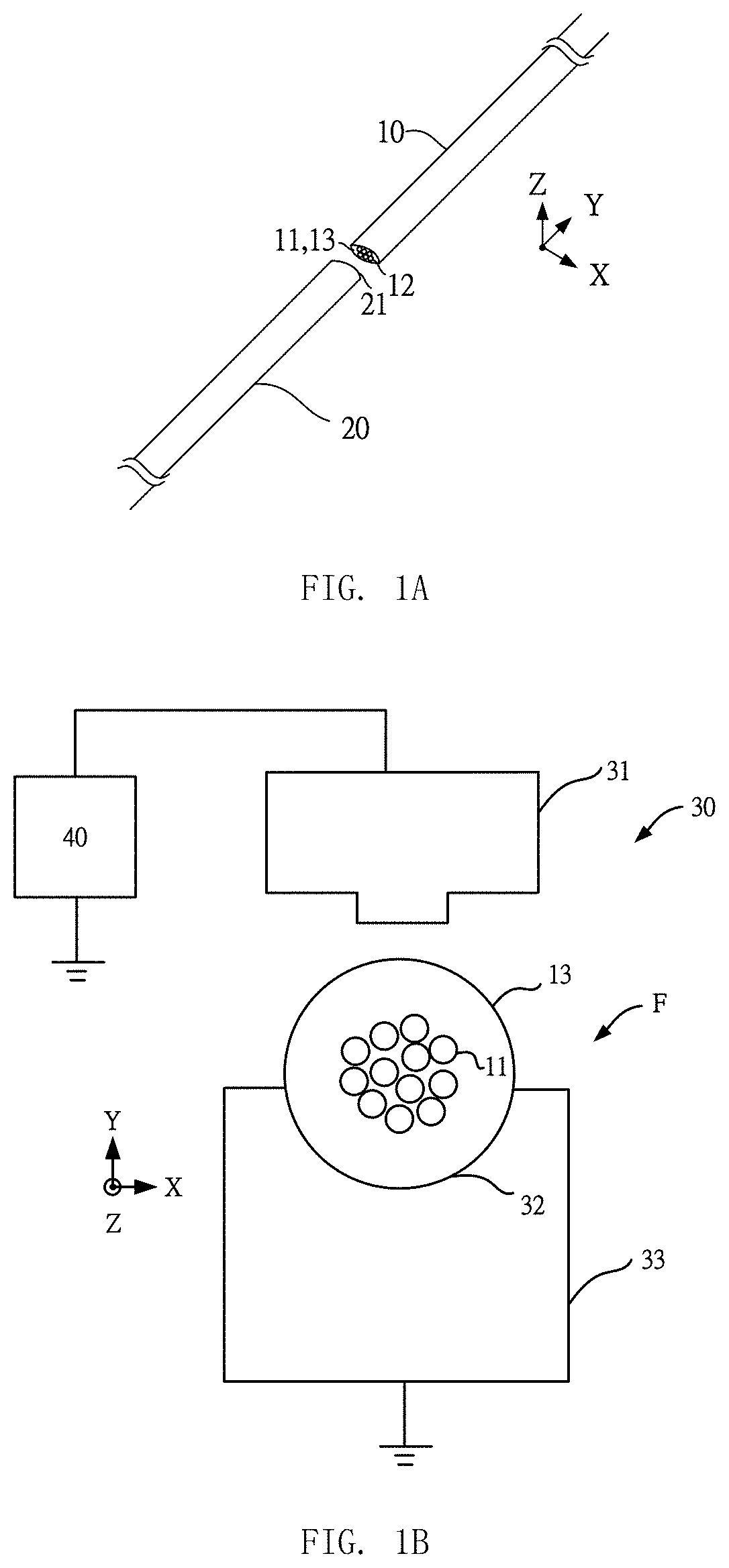
However, the existing fusing technology has the following problems: the fusing technology needs a higher current, but the higher current may easily make the indenter 31 oxidized.
Also, a long-term use of indenter 31 may leave stain, and the stain will cause the power supply 40 to be unstable, and the power supply 40 is easily damaged.
It not only consumes electricity, but also has a small resistance of the indenter 31, resulting in the low overall electric energy and heat energy conversion efficiency and waste of a lot of energy.
Thus, the workpiece F to be processed is heated without deformation cannot be achieved.
Therefore, the size of the workpiece is difficult to be controlled after the fusing technology is completed.
It is obvious that the existing fusion technology is only applicable to the manual work situation, and it is more difficult to apply to the automated work situation.
The impurity seriously affects the rate of the temperature rise and decrease conversion efficiency of the overall electrical energy and heat energy, thereby affecting the fusion welding quality.
Also, if the impurity is scratched out by a manual method before the fusing technology is performed, it will increase the production cost.

Method used


Image

  • An inductive thermo-crimping apparatus
  • An inductive thermo-crimping apparatus
  • An inductive thermo-crimping apparatus

Examples


Embodiment Construction

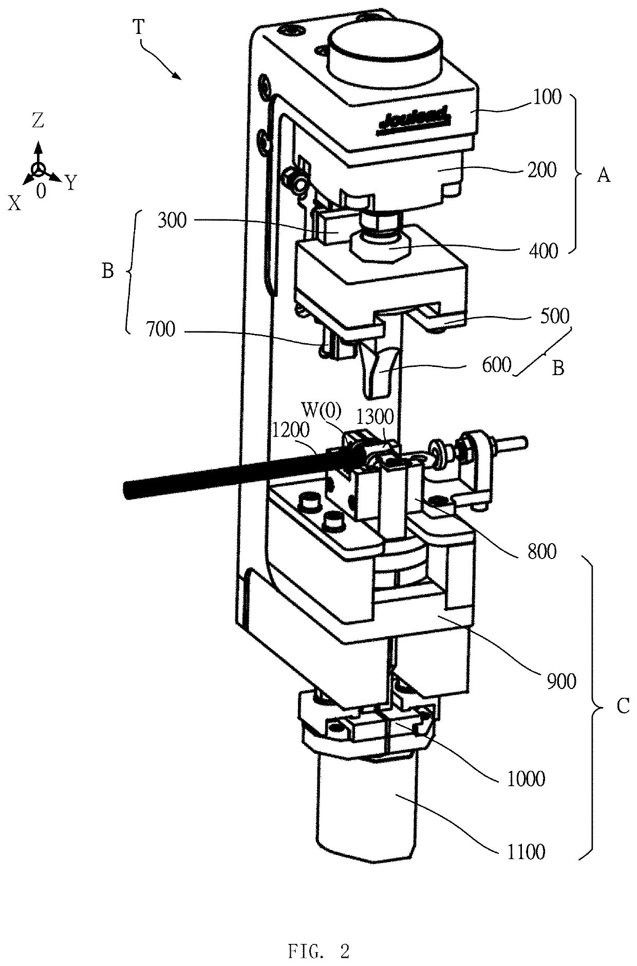
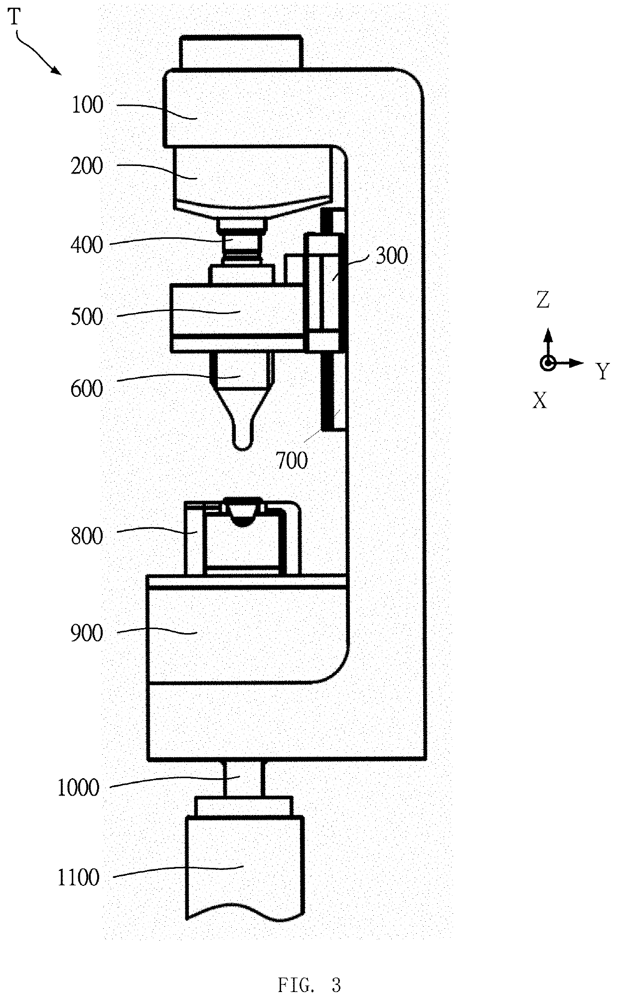
[0021]In order to provide a better understanding for the object, characteristics and advantages of the present invention to persons skilled in art and thus to embody the present invention, the accompanying drawings, embodiments provided to demonstrate the characteristics of the present invention and preferred embodiments serve to provide a further explanation. The accompanying drawings serve to express the illustrations for the characteristics of the present invention, so it is not needed to draw precisely. The embodiments regarding the technical content which is well-known by the technical persons in the related field may not be described in the specification as well.

[0022]In the present invention, X axis, Y axis and Z axis are the right-handed Cartesian coordinate system. In the present invention, the directions of X axis, Y axis and Z axis and origin are illustrated according to each figure, wherein the direction of X axis is the first direction, the direction of Y axis is the se...


PUM

PropertyMeasurementUnit
currentaaaaaaaaaa
temperatureaaaaaaaaaa

Abstract

An inductive thermo-crimping apparatus is provided, which is provided for crimping a crimping body which is formed by the contact of the connecting body and the to-be-joined member. The inductive thermo-crimping apparatus includes a driving part, a stamper part, and a heating part, the driving part is connected to the stamper part, and the heating part is fixedly connected to the driving part. After the heating part is activated, the crimping body is disposed on the heating part. The heating part includes an inductive heating coil. The inductive heating coil surrounds in the heating part. The inductive heating coil is provided for heating the crimping body to soften the crimping body, in which the driving part is provided for driving the stamper part to press the soften crimping body, so that the connecting body and the to-be-joined member is crimped and to form a rigid crimping body after cooling. The present invention utilizes the coil with an alternative current to heat the crimping body by an electromagnetic induction, so that the process of the crimping technology is convenient and fast.

Description

CROSS-REFERENCE TO RELATED APPLICATIONS[0001]This application claims the benefit of PCT / CN 2019 / 094361, filed on Jul. 2, 2019, the content of which are hereby incorporated by reference in their entirety.FIELD OF THE INVENTION[0002]The present invention is to provide an inductive thermo-crimping apparatus, more particularly a thermo-crimping apparatus of utilizing the induced Eddy current to heat a workpiece.BACKGROUND OF THE INVENTION[0003]The fusing technology is prevalent in the connecting process of the conducting wire. Please refer to FIG. 1A and FIG. 1B of the fusing technology in the prior arts. FIG. 1A illustrates a top view of two insulating electric wires 10 and 20. The insulating electric wire 10 has one or more copper wires 11 and an insulating layer 13 which covers the copper wires 11. Next, please together refer to FIG. 1A and FIG. 1B. FIG. 1B illustrates the side view of the fusing apparatus and the insulating electric wires, while the insulating electric wire is perfo...

Claims


Application Information

Patent Timeline
Patent Type & Authority Applications(United States)
IPC IPC(8): B29C65/46B29C65/20H01R43/048
CPCB29C65/46B29C65/20H01R43/048C21D1/26H01R43/02H01R4/187B23K20/004B23K20/00B23K2101/38B23K2103/12B23K2103/18B23K2103/42H05B6/14
Inventor CAO, JINTAILU, FEIMO, SHENGJIE
Owner SHANGHAI JOULEAD ELECTRIC CO LTD
Learn More