Systems for Blade Sharpening and Contactless Blade Sharpness Detection

a technology of contactless blades and blades, which is applied in the field of knife and blade sharpness testing, can solve the problems of incongruity and haphazardness, difficult to ascertain the sharpness of a given blade, and equally difficult to determine the sharpness of blades in relation to other parts of the blade, so as to avoid unnecessary material removal. , the effect of effective and efficien

Active Publication Date: 2020-11-19
TSUKANOV VITALY +3
View PDF5 Cites 3 Cited by
  • Summary
  • Abstract
  • Description
  • Claims
  • Application Information

AI Technical Summary

Benefits of technology

[0017]A further object of the invention is to enable blades to be sharpened in an effective and efficient manner while avoiding unnecessary material removal.
[0018]These and in all likelihood further objects and advantages of the present invention will become obvious not only to one who reviews the present specification and drawings but also to those who have an opportunity to make use of an embodiment of the system for blade sharpening and contactless blade sharpness detection disclosed herein. However, it will be appreciated that, although the accomplishment of each of the foregoing objects in a single embodiment of the invention may be possible and indeed preferred, not all embodiments will seek or need to accomplish each and every potential advantage and function. Nonetheless, all such embodiments should be considered within the scope of the present invention.

Problems solved by technology

However, establishing and maintaining the desired sharpening angle during the sharpening process can be challenging so that the results are often inconsistent and haphazard.
Unfortunately, during the sharpening process, it is difficult to ascertain the sharpness of a given blade.
It is equally challenging to determine the sharpness of portions of the blade in relation to other portions of the blade.
More generally, determining when a user should move from one stage of the sharpening process to the next, such as to a stage of finer grinding or to polishing, can be difficult, particularly for the typical home user.
Improperly advancing from one sharpening stage to the next can result in the excess removal of metal from the blade and increased blade processing time.
Continuing rough grinding of a blade or a portion of the blade where it is already ready for fine grinding wears the blade unnecessary, but moving to fine grinding when further rough grinding is needed consumes excess time and effort.
Moreover, continuing to focus on a portion of the blade that is already sufficiently prepared in a given stage of sharpening leads to unnecessary material removal at that portion just as failing to focus on a portion of the blade that requires further finishing leads to uneven results and wasted time.
The relative complexity of blade sharpening and the inability to verify blade sharpness during the sharpening process contribute to poor results and increased user uncertainty and confusion.
Disadvantageously, haptic estimation of sharpness is very subjective.
Cutting through test objects can itself present a danger to the user and requires access to sufficient testing substrate.
Still further, predetermined instructions are often not matched to the actual condition of a given blade.
Each method may improperly focus only on one or more specific portions of a blade while other portions may not match the sharpness condition of the tested portion.
Such systems, however, require a separate device, and they assume the proper contact between the sharp edge and the test object, which increases probability of damaging or distorting the cutting edge by the very object that is designed to test it.
Unfortunately, these too suffer from important limitations.
For example, while it describes a receptor slot for a blade, Lebeau's Optical Sharpness Meter of Publication No. 20060192939A1 does not teach how a blade can be engaged or moved in relation to the slot without deleteriously impacting the blade's sharpness.
EP0866308A3 teaches an apparatus for determining the profile of an object, such as an edge on an aircraft engine blade, but it does not teach how a knife blade might be engaged and advanced in a sharpness detection system.

Method used


Image

  • Systems for Blade Sharpening and Contactless Blade Sharpness Detection
  • Systems for Blade Sharpening and Contactless Blade Sharpness Detection
  • Systems for Blade Sharpening and Contactless Blade Sharpness Detection

Examples


Embodiment Construction

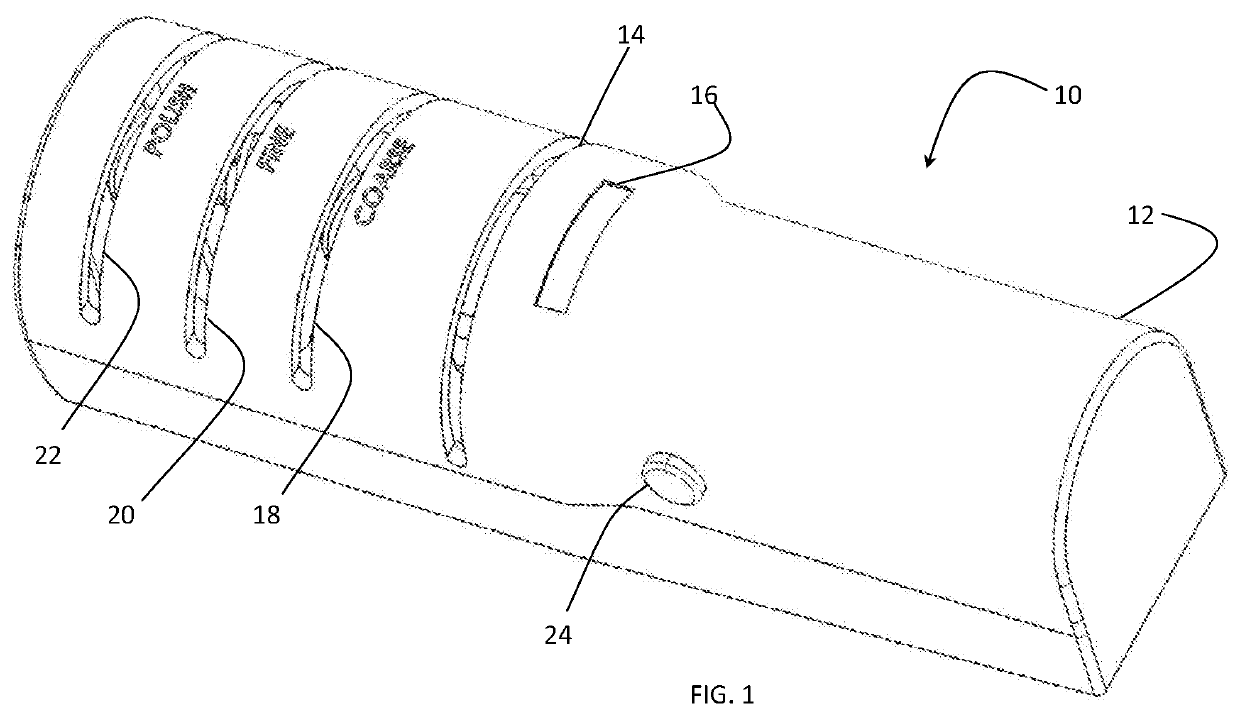
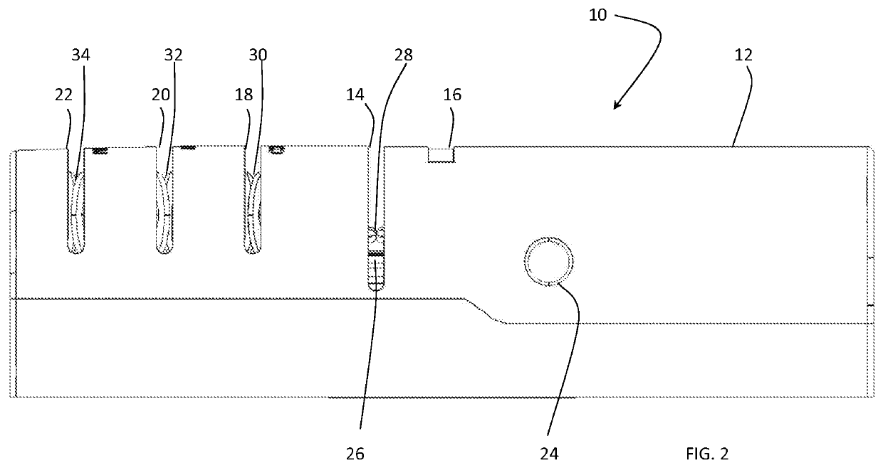
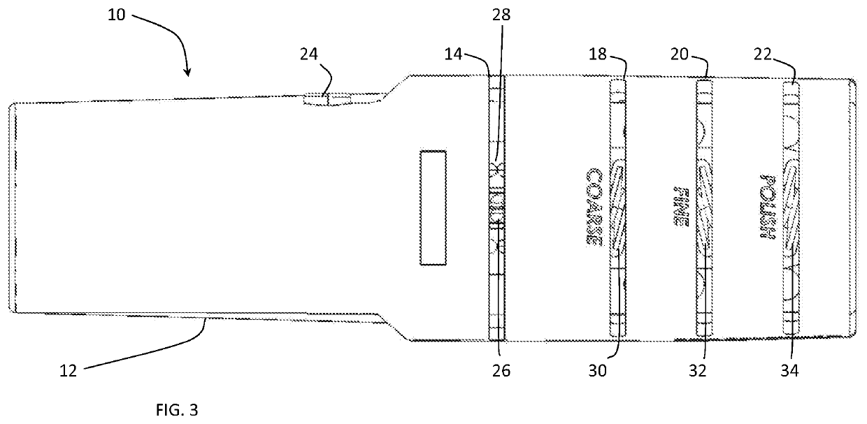
[0050]The systems for blade sharpening and contactless blade sharpness detection disclosed herein are subject to a wide variety of embodiments. However, to ensure that one skilled in the art will be able to understand and, in appropriate cases, practice the present invention, certain preferred embodiments of the broader invention revealed herein are described below and shown in the accompanying drawing figures.

[0051]The systems for blade sharpening and contactless blade sharpness detection disclosed herein may be employed to great advantage where blade sharpening and blade sharpness detection are enabled in a single device. However, it is to be understood that contactless blade sharpness detection systems according to the invention could be employed independently and that the present blade sharpening system could be exploited in combination with differently embodied blade sharpness detection systems or vice versa. The scope of the invention shall be limited only as may be expressly ...


PUM

PropertyMeasurementUnit
cutting edge angleaaaaaaaaaa
diametersaaaaaaaaaa

Abstract

A blade sharpness detection system for determining a sharpness of a blade and a combined blade sharpening and blade sharpness detection system for permitting both blade sharpening and a determination of blade sharpness without mechanical contact with the cutting edge of the blade. An optical inspection unit is operative to inspect blade sharpness optically, and a blade positioning and guidance mechanism is disposed to position and guide the blade in relation to the optical inspection unit. An output display is operative to provide a visual output of the sharpness of the blade. The optical inspection unit, which can be a reflective optical sensor, and the blade positioning and guidance mechanism are retained by a pivotable support structure. The positioning and guidance mechanism can be formed by first and second pairs of rotatable spheres, each pair of rotatable spheres disposed in immediate juxtaposition to act as rolling supports for the blade.

Description

RELATED APPLICATION[0001]This application claims priority to Provisional Application No. 62 / 849,446, filed May 17, 2019, Provisional Application No. 62 / 926,000, filed Oct. 25, 2019, and Provisional Application No. 62 / 966,306, filed Jan. 27, 2020, each of which being incorporated herein by reference.FIELD OF THE INVENTION[0002]The present invention relates generally to knife and blade sharpness testing. More particularly, disclosed herein are methods and devices for inspecting blade cutting edge sharpness in a contactless manner and for blade sharpening, potentially in a unitary system, to permit ongoing inspection and verification of blade sharpness to maximize the ability to achieve a high level of blade sharpness while minimizing unnecessary material removal during rough and fine grinding and polishing.BACKGROUND OF THE INVENTION[0003]A well-performing knife or other bladed cutting instrument will have a sharp blade formed according to its purpose. A knife blade has a wedge angle,...

Claims


Application Information

Patent Timeline
Patent Type & Authority Applications(United States)
IPC IPC(8): B24B3/54B24B51/00
CPCB24B51/00B24B3/54
Inventor TSUKANOV, VITALYBASHTYK, YURAROMANYSHYN, IVANELLIS, JOHN R.
Owner TSUKANOV VITALY
Why Eureka
Try Eureka