Desalination system and method

a desalination system and technology of a desalination system, applied in the field of water filtering, can solve the problems of high process cost and the current process of generating and delivering fresh water to the market is still expensive, and achieve the effect of enhancing the energy saving of the system and being more controllable and reliabl

Active Publication Date: 2020-11-19
EVANS ROBERT B +1
View PDF0 Cites 1 Cited by
  • Summary
  • Abstract
  • Description
  • Claims
  • Application Information

AI Technical Summary

Benefits of technology

The present systems and methods described in this patent allow for the controlled ascent or descent of objects in a body of salt water. This is achieved through the use of an osmotic module that produces fresh water in a controlled fashion, which can provide a lifting force for raising objects from the bottom of the sea in a controlled fashion. The method is more controllable and reliable than using air filled bladders as the lifting force is more constant during ascent. The systems also allow for gently lowering objects to the sea bottom without the use of complicated and expensive cranes. The use of an osmotic module placed below the diel or diurnal vertical migration depth of organisms living in sea or fresh water bodies eliminates the need for pre-filtering stages upstream of the module, which enhances the energy savings of the system as compared to surface-operated systems.

Problems solved by technology

These processes are expensive at least because they require large amounts of energy to heat water for distillation or to pump water through membranes.
While the use of alternative energy sources to reduce the cost of the process of generating and delivering fresh water is a promising endeavor, current processes of generating and delivering fresh water to market are still expensive.

Method used


Image

  • Desalination system and method
  • Desalination system and method
  • Desalination system and method

Examples


Embodiment Construction

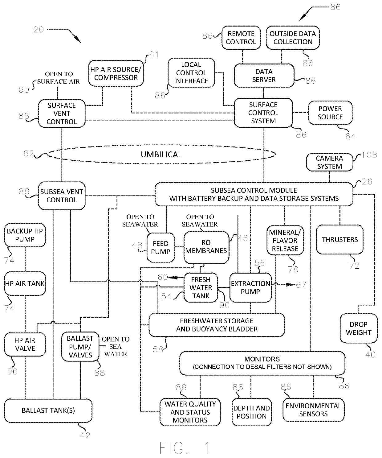
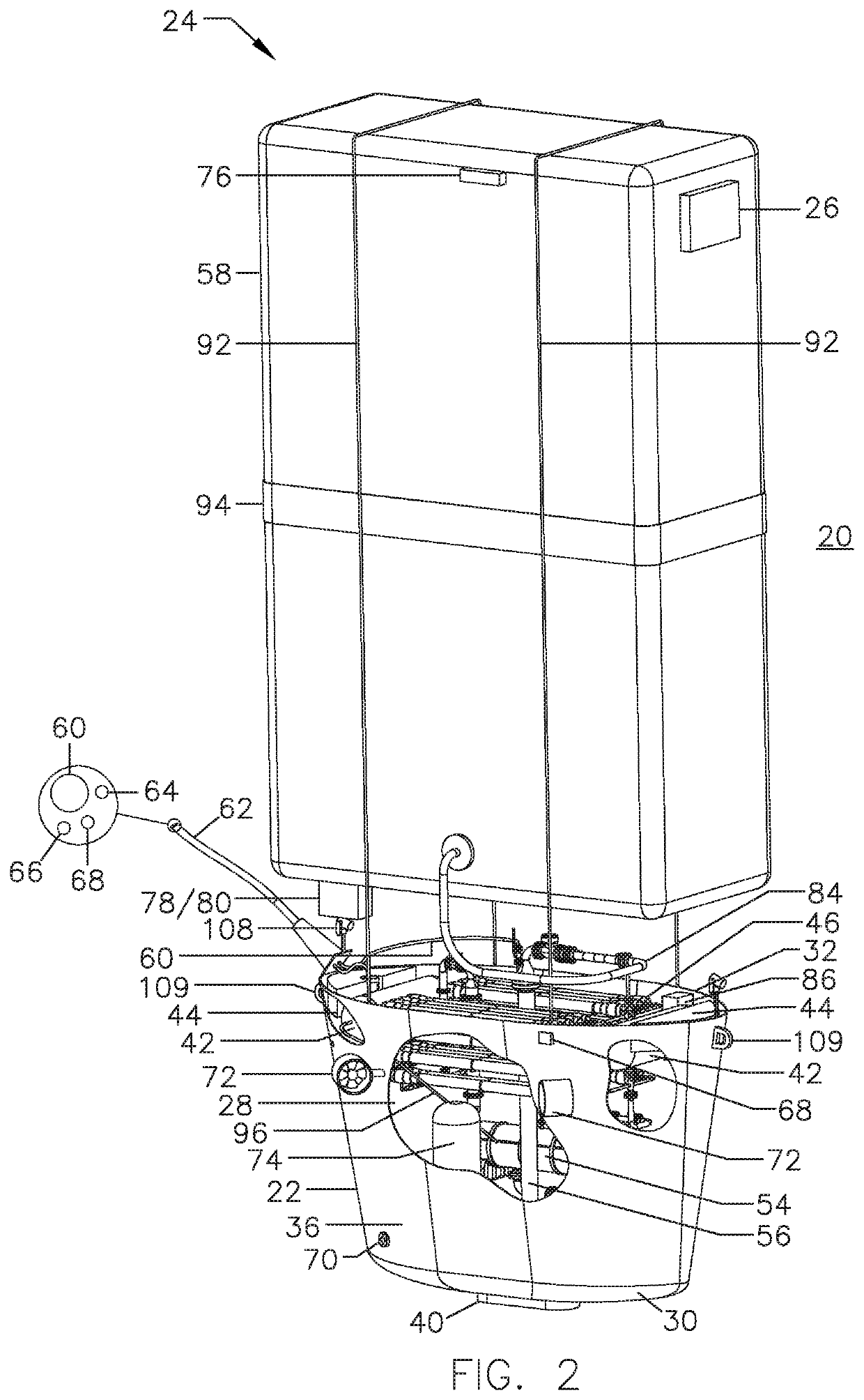
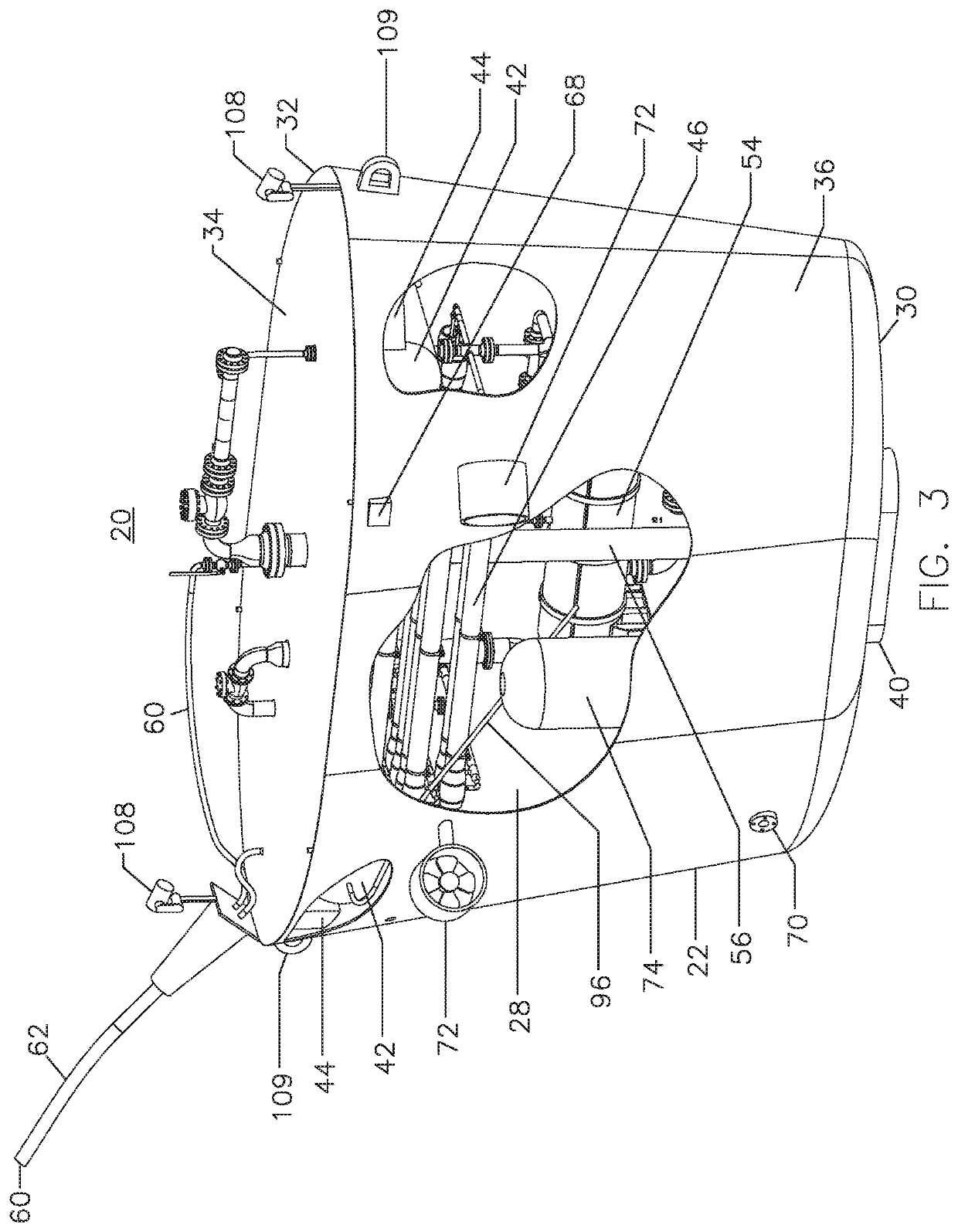
[0019]Reference will now be made in detail to specific embodiments or features, examples of which are illustrated in the accompanying drawings. Wherever possible, corresponding or similar reference numbers will be used throughout the drawings to refer to the same or corresponding parts. Moreover, references to various elements described herein are made collectively or individually when there may be more than one element of the same type. However, such references are merely exemplary in nature. It may be noted that any reference to elements in the singular may also be construed to relate to the plural and vice-versa without limiting the scope of the disclosure to the exact number or type of such elements unless set forth explicitly in the appended claims. The terms configured and configuration may be used herein to refer to a specified structural size and shape.

[0020]Referring to the embodiments illustrated in FIGS. 1-5, the filter system 20 includes a vessel 22. The system 20 includ...


PUM

PropertyMeasurementUnit
energyaaaaaaaaaa
naturally occurring forcesaaaaaaaaaa
currentaaaaaaaaaa

Abstract

A desalination system that is deployable in a body of water having a surface and a seafloor and which includes a vessel structure that is capable of travel in water, a reverse osmosis system disposed within an internal space of the vessel structure and a tank connected to the reverse osmosis system, the tank configured to receive filtered water from the reverse osmosis system. A positioning system is provided for controlling the travel of the vessel structure, and a ballast system is configured to control the buoyancy of the vessel structure. A controller is operably associated with the positioning system and the ballast system to control the position of the vessel below the surface of the body of water.

Description

CROSS-REFERENCE TO RELATED APPLICATIONS[0001]This patent application claims the benefit of U.S. Provisional Patent Application No. 62 / 544,400, filed Aug. 11, 2017, which is incorporated in its entirety herein by this reference.TECHNICAL FIELD[0002]The present disclosure relates to water filtering. The present disclosure also relates to buoyancy control and methods and systems related to the transport, deployment, and recovery of water filtering systems.BACKGROUND[0003]The conversion of sea water to fresh water is presently performed by distillation or reverse osmosis processes. These processes are expensive at least because they require large amounts of energy to heat water for distillation or to pump water through membranes. Attempts have been made to use naturally occurring forces to augment at least part of these processes and to offset the cost of operating such systems. While the use of alternative energy sources to reduce the cost of the process of generating and delivering fr...

Claims


Application Information

Patent Timeline
Patent Type & Authority Applications(United States)
IPC IPC(8): C02F1/44B01D61/02B01D61/08B01D61/10B01D61/12
CPCC02F2201/008B01D2313/90B01D61/08B01D2315/06B63G8/22C02F2103/08B01D61/025C02F1/441B01D61/10B01D61/12Y02A20/131B01D2313/203B01D2313/2031B01D2313/501B01D2313/50B01D2313/903
Inventor EVANS, ROBERT B.CHESS, SUSANNE E.
Owner EVANS ROBERT B
Why Eureka
Try Eureka