
Source-based routing

a technology of source-based routing and communication network, which is applied in the direction of data switching network, digital transmission, electrical equipment, etc., can solve the problems of incorrect packet routing of packets, large number of service configuration of ssrs, and inability to have visibility into ssrs

Active Publication Date: 2020-11-19
128 TECH
View PDF0 Cites 40 Cited by
  • Summary
  • Abstract
  • Description
  • Claims
  • Application Information

AI Technical Summary

Benefits of technology

The invention is a routing system for routing packets for a route or service. The system includes a source router that receives service and topology information from other routers and determines a first path to a destination based on this information. The source router then sends a packet with metadata that includes information about the remaining routers in the path to receive the packet. Each successive router in the path receives the packet, removes its own metadata, and forwards the packet to the next router in the path. The destination router then sends the packet with its own metadata. This allows for efficient routing of packets and ensures that each router can properly handle the traffic.

Problems solved by technology

As discussed above, service configuration of a large number of SSRs can be difficult.
Furthermore, SSRs currently do not have visibility into whether a service is available at the ultimate destination (last hop).
This lack of visibility, from a networking perspective, can lead to incorrect routing of packets.
This does not scale well across multiple SSRs.
Currently, SSRs work around this limitation using path and interface failover techniques that will not work in all cases, especially when there is total outage and when the services are unavailable on other routers as well.
There are several deployments where the connectivity to the Conductor is unreliable and may not be available for extended periods of time such that the routers would not be able to talk to each other.
Since SSR routing is service oriented, the peer paths themselves do not give a complete picture of the service availability.
A router may be become unavailable for any of a variety of reasons, such as, for example, a failure of the router, unavailable or poor communication connectivity to the router, a shutdown of the router by a network administrator, or removal of the router from the network configuration (e.g., through a notification to the STEP server).
Since legacy routing protocols are not aware of vectors, the cost of the route is used directly.
However, this is not considered a normal mode of operation and should be the least preferred way of advertising routes, as STEP is not considered as a protocol to carry legacy routes across the network.
However, there may be cases where this needs to be overridden on a per-interface basis.
It also should be noted that in the above example, the headend (source) router replicates packets to all other routers and there is no multicast tree used for this distribution of packets, and as more branch routers are added, the headend replication can become too inefficient.
Providing encryption in the multicast proxy scheme is more complex because there are multiple receivers, although, for example, a common set of encryption keys can be distributed to all receivers so that the source packets can be encrypted once for all receivers.
This causes a loop in the network.
Thus, there is nothing conventional about the inventions described herein because even when embodiments are implemented using conventional components, the resulting devices and systems (e.g., the STEP server controller and STEP client controller) are necessarily non-conventional because, absent special programming or configuration, the conventional components do not inherently perform the described non-conventional functions.
These solutions as a whole are not well-understood, routine, or conventional and in any case provide practical applications that transform and improve computers and computer routing systems.

Method used


Image

  • Source-based routing
  • Source-based routing
  • Source-based routing

Examples


Embodiment Construction

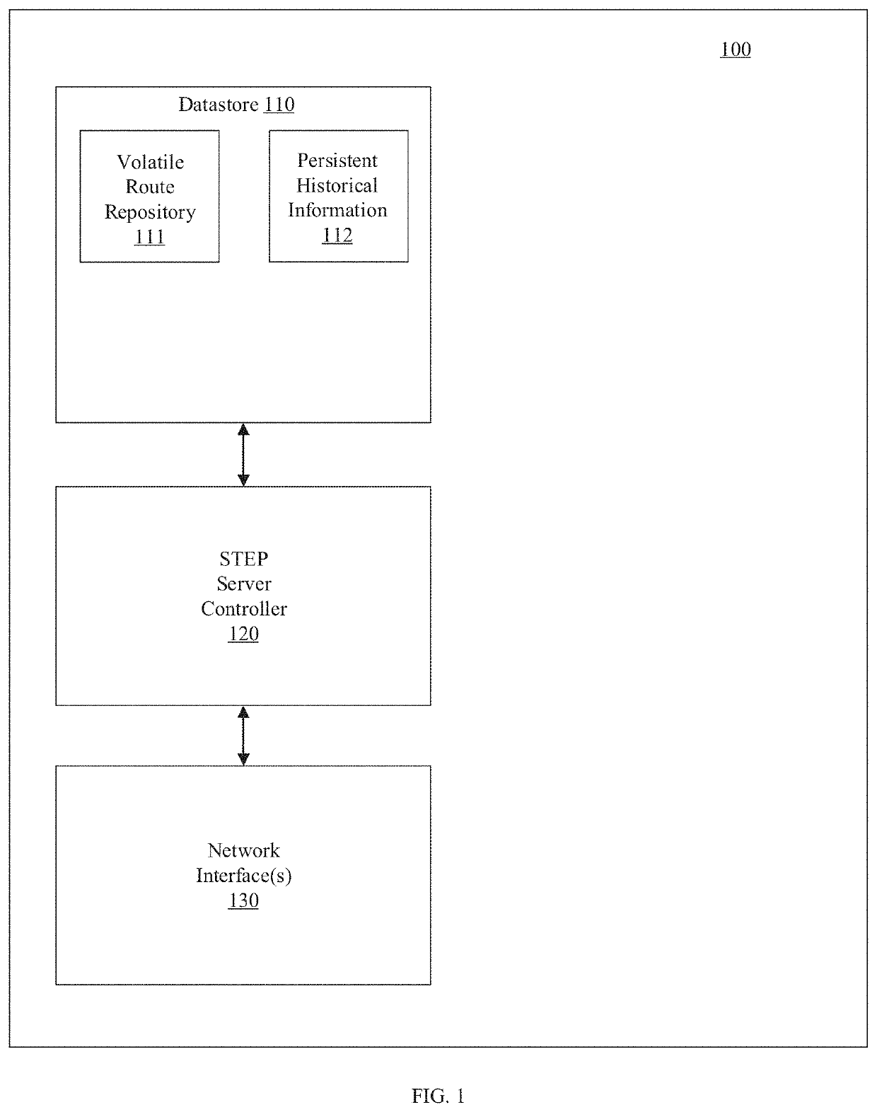
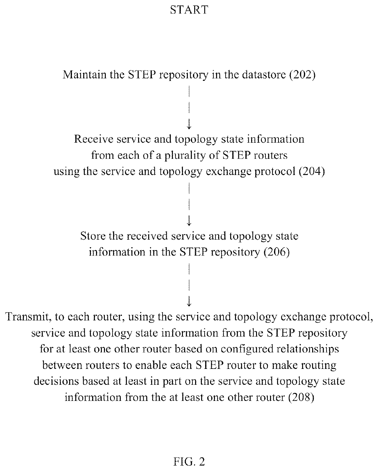
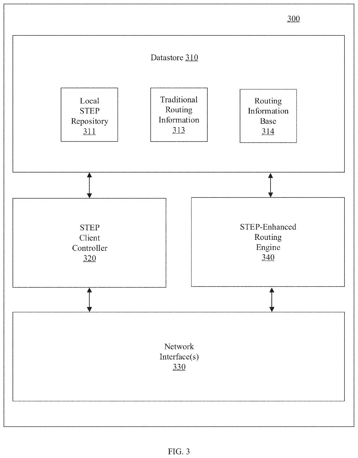
[0007]In accordance with one embodiment of the invention, a routing system for routing packets for a route or service comprises a plurality of routers including a source router. The source router is configured to receive, using a service and topology exchange protocol, service and topology state information from a STEP repository for at least one other router based on configured relationships between routers; determine a first path to a destination for a route or service based on the service and topology state information, the first path including an ordered list of successive routers to receive a packet associated with the route or service starting with a first successive router and ending with a destination router; and transmit a packet toward the first successive router with first metadata including a list of at least one remaining router of the ordered list of routers to receive the packet associated with the route or service. Each successive router, starting with the first succ...


PUM


Abstract

A routing system for routing packets for a route or service comprises a plurality of routers including a source router, wherein the source router is configured to receive, using a service and topology exchange protocol, service and topology state information from a STEP repository for at least one other router based on configured relationships between routers; determine a first path to a destination for a route or service based on the service and topology state information, the first path including an ordered list of successive routers to receive a packet associated with the route or service starting with a first successive router and ending with a destination router; and transmit a packet toward the first successive router with first metadata including a list of at least one remaining router of the ordered list of routers to receive the packet associated with the route or service. Each successive router, starting with the first successive router, is configured to receive a packet and determine if the router is the destination router based on metadata associated with the received packet, and when the router is not the destination router, forward the packet toward a next successive router in the ordered list of routers.

Description

CROSS-REFERENCE TO RELATED APPLICATION(S)[0001]This patent application is related to U.S. patent application Ser. No. 15 / 054,781 filed Feb. 26, 2016 (now issued U.S. Pat. No. 9,985,883), entitled, “NAME-BASED ROUTING SYSTEM AND METHOD,” attorney docket number 4094 / 1014, and naming MeLampy, Baj, Kumar, Penfield, and Timmons as inventors, the disclosure of which is incorporated herein, in its entirety, by reference.[0002]This patent application also is related to U.S. patent application Ser. No. 14 / 833,571, filed Aug. 24, 2015 (now issued U.S. Pat. No. 9,762,485), entitled, “Network Packet Flow Controller with Extended Session Management,” attorney docket number 4094 / 1011, and naming Kaplan, Kumar, Timmons, and MeLampy as inventors, the disclosure of which is incorporated herein, in its entirety, by reference.FIELD OF THE INVENTION[0003]The invention generally relates to source-based routing in a communication network.BACKGROUND OF THE INVENTION[0004]A routing platform such as the 128...

Claims


Application Information

Patent Timeline
Patent Type & Authority Applications(United States)
IPC IPC(8): H04L12/721H04L45/02H04L45/24H04L45/60
CPCH04L45/34H04L45/28H04L45/50H04L45/245H04L45/60
Inventor KAPLAN, HADRIEL S.MENON, ABILASHTIMMONS, PATRICKBAJ, MICHAELPENFIELD, ROBERTMELAMPY, PATRICK
Owner 128 TECH
Learn More