Antenna pattern, RFID inlay, RFID label, and RFID medium

Active Publication Date: 2020-11-26
SATO HLDG CORP
View PDF0 Cites 0 Cited by
  • Summary
  • Abstract
  • Description
  • Claims
  • Application Information

AI Technical Summary

Benefits of technology

The patent improves the direction and range of the UHF frequency band RFID antenna by increasing its directivity. This allows for more efficient transmission and reception.

Problems solved by technology

The RFID inlay described in JP2010-237853A has a directivity in which a good gain is obtained in the crossing direction with respect to the direction in which the dipole antenna extends, but the gain is poor in the direction in which the dipole antenna extends, and there is a problem in that, when a reader / writer is located in the latter direction, a transmission and reception of data becomes unstable.
Therefore, in a case in which the RFID inlay is applied to, for example, an application in which entrance and exit of a holder of “ID-1” standard card specified in ISO / IEC 7810 is managed by mounting the RFID inlay on the card and an application in which a timing of finishing of a competitor is recorded by affixing the RFID inlay to a numbered bib, etc. of the competitor, there has been a problem in that transmission and reception of information cannot be performed correctly depending on an orientation of the RFID inlay or a positional relationship between the RFID inlay and an RFID reader.

Method used


Image

  • Antenna pattern, RFID inlay, RFID label, and RFID medium
  • Antenna pattern, RFID inlay, RFID label, and RFID medium
  • Antenna pattern, RFID inlay, RFID label, and RFID medium

Examples


first embodiment

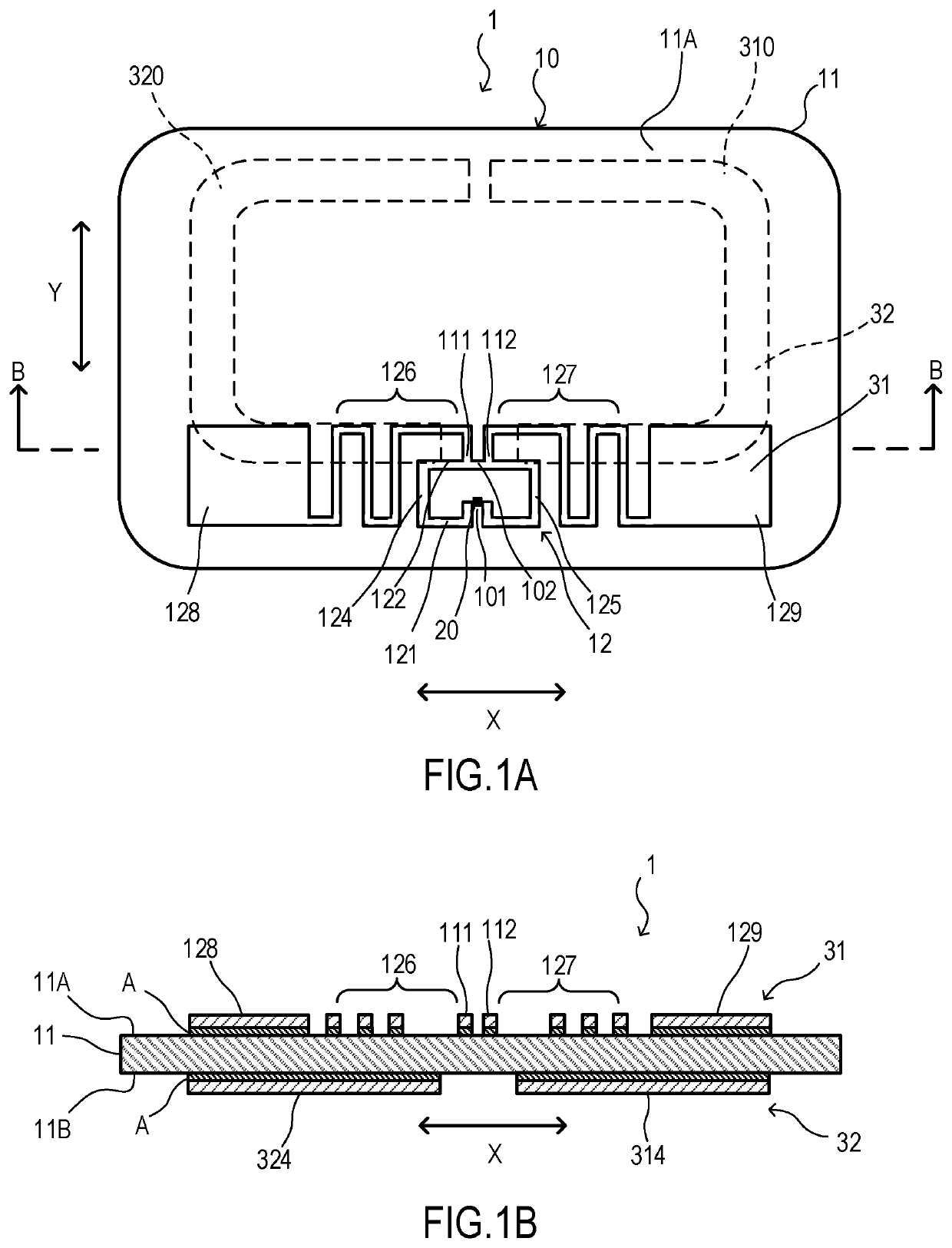
[0025]The RFID inlay 1 and an antenna pattern 10 according to a first embodiment of the present invention will be described. The RFID inlay 1 in this embodiment is a UHF frequency band RFID inlay.

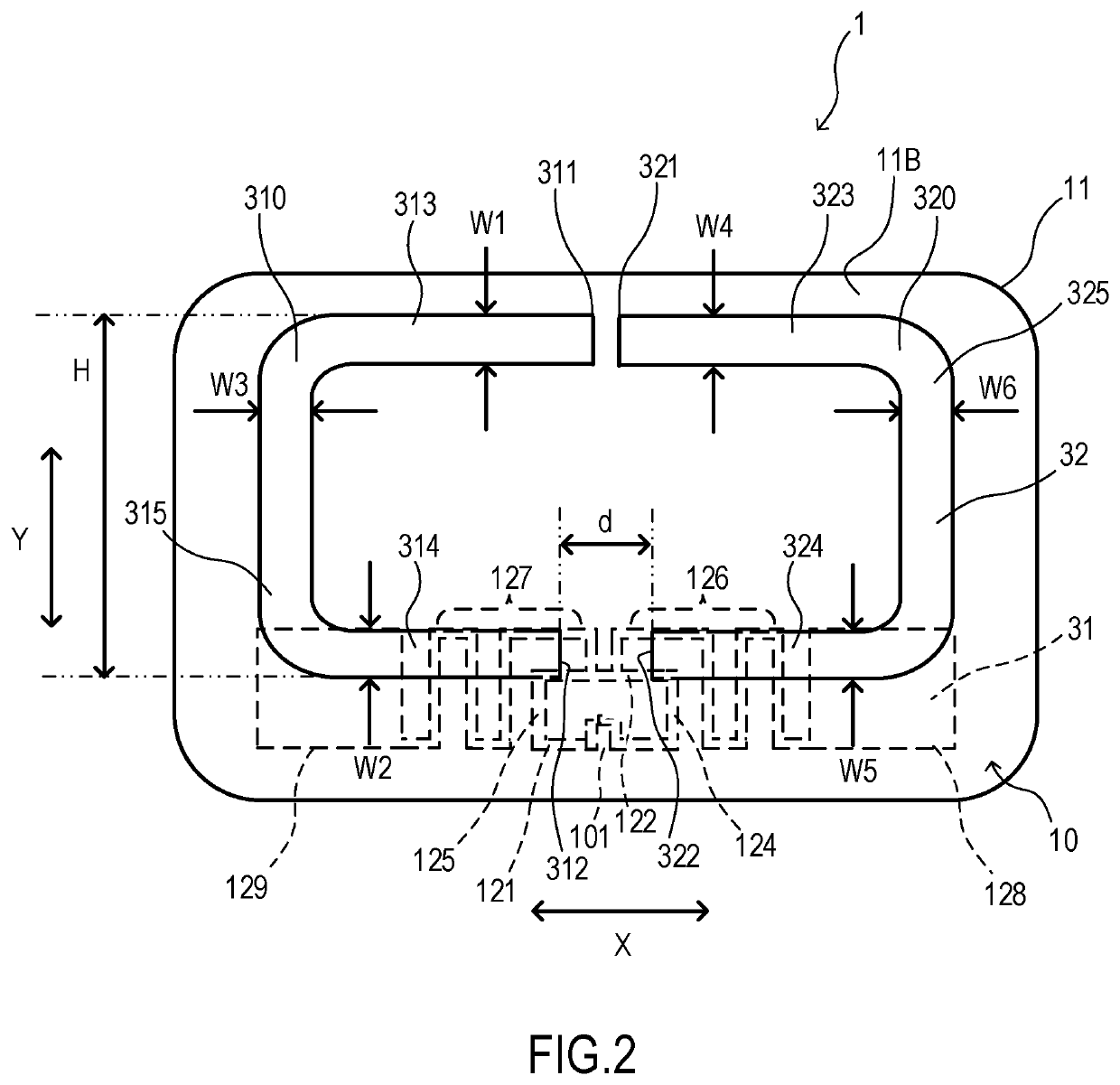
[0026]FIG. 1A is an external view for explaining a front surface of the RFID inlay 1 according to the first embodiment, and FIG. 1B is a sectional view taken along a line B-B in FIG. 1A. In addition, FIG. 2 is an external view for explaining a back surface of the RFID inlay 1 according to the first embodiment.

[0027]In this embodiment, in the RFID inlay 1, an IC chip 20 with an RFID (Radio Frequency Identification) specification is bonded to the antenna pattern 10 by a vulcanization bonding, etc. using an anisotropic conductive paste or a conductive film.

[0028]The antenna pattern 10 is provided with a dipole antenna 31 that is formed on a front surface 11A of a substrate 11 with a metal foil and a sub-element 32 that is formed on a back surface 11B of the substrate 11 with the metal foil. As...

second embodiment

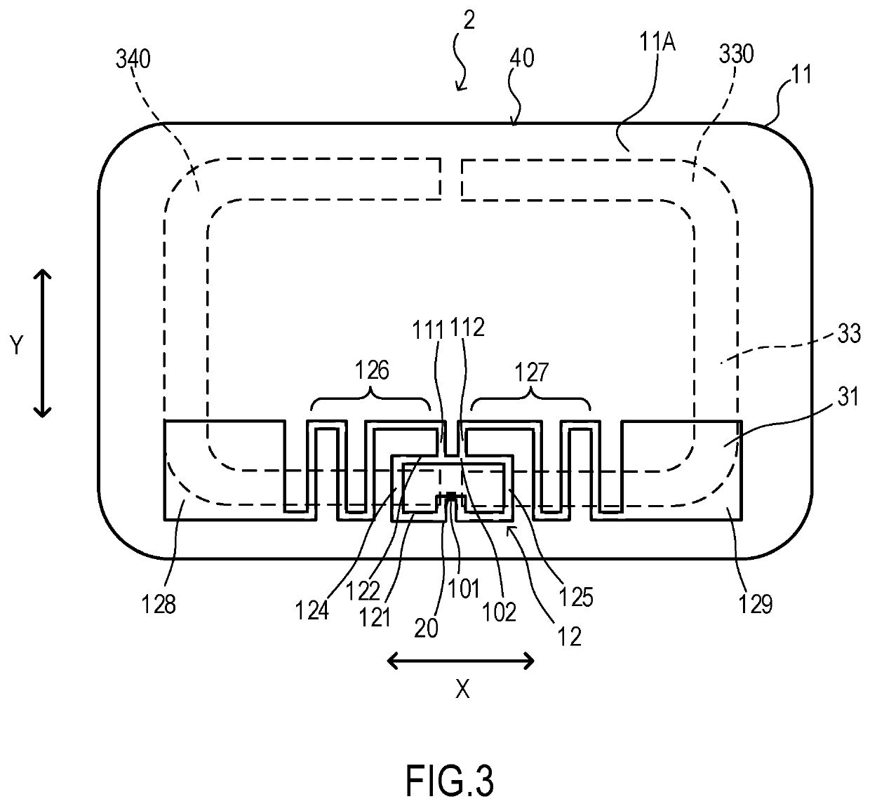
[0058]An RFID inlay 2 and an antenna pattern 40 according to a second embodiment of the present invention will be described. In the second embodiment, a positional relationship between the dipole antenna 31 and a sub-element 33 is modified. In other words, the length H of the sub-element 33 in the Y direction is longer than that of the sub-element 32. In addition, the gap d between base end portions 332 and 342 is reduced.

[0059]FIG. 3 is an external view for explaining a front surface of the RFID inlay 2 according to the second embodiment. In addition, FIG. 4 is an external view for explaining a back surface of the RFID inlay 2 according to the second embodiment. Configurations that have the same functions as the configurations shown in the first embodiment are assigned the same reference signs, and detailed descriptions thereof shall be omitted.

[0060]In the RFID inlay 2 that is shown as the second embodiment, the antenna pattern 40 has the substrate 11, the loop portion 12 that is ...

third embodiment

[0070]An RFID inlay 3 and an antenna pattern 50 according to a third embodiment of the present invention will be described. In the third embodiment, a sub-element 34 formed in the antenna pattern 50 is formed to have a shape in which base end portions 352 and 362 of the U-shape of elements 350 and 360 are each bent outwards of the U-shape. In other words, each of the elements 350 and 360 has a fishhook-like shape.

[0071]FIG. 5 is an external view for explaining a front surface of the RFID inlay 3 according to the third embodiment. In addition, FIG. 6 is an external view for explaining a back surface of the RFID inlay 3 according to the third embodiment. Configurations that have the same functions as the configurations shown in the first embodiment are assigned the same reference signs, and detailed descriptions thereof shall be omitted.

[0072]In the RFID inlay 3 shown as the third embodiment, the antenna pattern 50 has the substrate 11, the loop portion 12 formed on the front surface ...


PUM


Abstract

An antenna pattern used in a UHF frequency band RFID inlay is provided with a substance; a dipole antenna formed from a metal foil upon the front surface of the substance; and a sub-element formed from a metal foil upon the back surface of the substance, wherein the dipole antenna is provided with a loop portion having a IC chip connecting portion; a pair of meanders configured to respectively extend from the loop portion so as to be line symmetrical; and capacitance hats, the sub-element has a pair of U-shapes, and a part of the sub-element overlaps with the dipole antenna through the substance.

Description

TECHNICAL FIELD[0001]The present invention relates to an antenna pattern applied to a UHF frequency band RFID, an RFID inlay, an RFID label, and an RFID medium.BACKGROUND ART[0002]In the field of manufacture, management, logistics, and so forth of products, tags that are attached to the products and labels that are adhered to the products, etc. are used. Information related to the products are printed on the tags and the labels so as to be visible. In recent years, a technique utilizing an RFID (Radio Frequency Identification), in which identification information written on an IC chip is transmitted and received via a wireless communication, is becoming more and more common in various fields, and the technique is also becoming more familiar in the above-described fields.[0003]On the tag, the label, an wrist band, and so forth (hereinafter, referred to as an RFID medium) incorporated an antenna pattern and the IC chip with an RFID specification as described above, information related...

Claims


Application Information

Patent Timeline
IPC IPC(8): H01Q9/26H01Q19/02H01Q1/22H01Q9/28
CPCH01Q1/2208H01Q9/28H01Q9/265H01Q19/02G06K19/077H01Q9/26B42D25/305H01Q9/065H01Q1/38H01Q1/2225H01Q7/00G06K19/07794G06K19/07767H01Q9/285G06K19/07786G06K19/07722G06K19/0776G06K19/0723H01Q9/24
Inventor ESCARO, RODLYMAEDA, YOSHIMITSUADIB, FAIZ ADI EZARUDIN BIN
Owner SATO HLDG CORP
Why Eureka
Try Eureka