Wideband GNSS antenna system

a global navigation satellite and receiver antenna technology, applied in the direction of resonant antennas, polarised antenna unit combinations, instruments, etc., can solve the problems of poor gain at the horizon, and achieve the effects of improving efficiency, low loss, and high efficiency

Active Publication Date: 2020-09-03
HEMISPHERE GNSS
View PDF0 Cites 5 Cited by
  • Summary
  • Abstract
  • Description
  • Claims
  • Application Information

AI Technical Summary

Benefits of technology

[0005]The disclosed structure antenna system provides an ideal gain pattern for GNSS receivers. The antenna system uses a parasitic loop fed by a cross dipole antenna, in a single plane. The dipole antenna is also part of the radiating element. Using a feed network as part of the radiating structure increases efficiency. The loop provides low elevation gain which the cross dipole cannot. The antenna structure is separated from a low-noise amplifier (LNA) PCB acting as a ground plane, with spacers and an air gap between the antenna elements and ground plane, such that the air gap is used as a dielectric between the antenna element and the ground plane. The air dielectric, having no ceramic or plastic, provides for low losses (higher efficiency) and low cost, but typically creates an issue with the edges being 180 degrees apart, causing very poor gain at the horizon. However, by not using a dielectric other than air, the useful bandwidth is increased. To compensate for the low elevation gain, the feed (cross dipole) is meandered, or spiraled, such that it has resonant ¼ wavelength-long arms that fit within the loop. The loop, being approximately 1 wavelength in circumference (required for resonance), has a radius of wavelength / 2π, or approximately ⅙ of a wavelength. This provides low elevation gain required for INMARSAT tracking. The gain pattern may be adjusted by coupling tuning capacitors to the loop.

Problems solved by technology

The air dielectric, having no ceramic or plastic, provides for low losses (higher efficiency) and low cost, but typically creates an issue with the edges being 180 degrees apart, causing very poor gain at the horizon.

Method used


Image

  • Wideband GNSS antenna system
  • Wideband GNSS antenna system
  • Wideband GNSS antenna system

Examples


Embodiment Construction

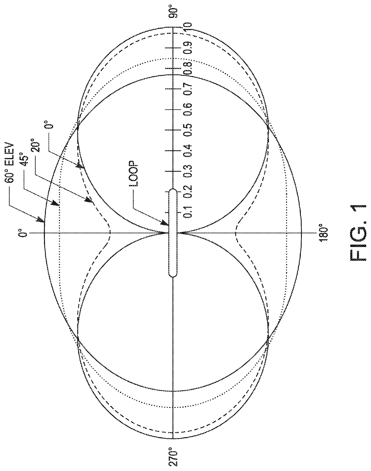
[0018]Referring to the drawings, FIG. 1 is a side view of a conventional loop antenna without a ground plane, having gain patterns associated with the antenna superimposed over the antenna. This generally illustrates the expected gain at various locations relative to the antenna. As shown, the highest gain of the loop antenna is in line with the plane of the loop (270 degrees and 90 degrees). As shown, the lowest gain of the loop antenna occurs at approximately 0 degrees and 180 degrees.

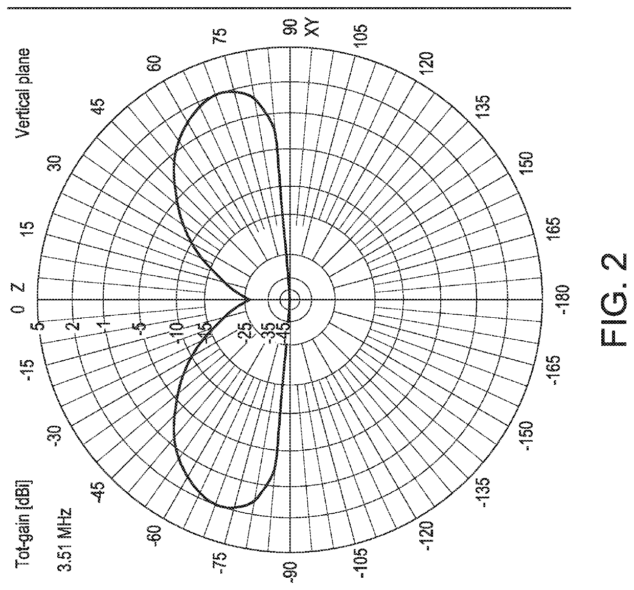
[0019]FIG. 2 shows the gain pattern of a conventional loop antenna with a ground plane. As shown in FIG. 2, the line passing through −90 degrees, the origin, and +90 degrees is referred to as the “horizon.” As shown, the loop antenna over a ground plane has null (0) gain directly over the horizon (from approximately −90 degrees to −85 degrees, and from approximately +85 degrees to +90 degrees), but is still optimized (providing high gain) at low angles (approximately −75 degrees to −45 degrees, and +...


PUM


Abstract

A complex and intricate GNSS antenna that is created using inexpensive manufacturing techniques is disclosed. The antenna combines a loop antenna and a cross dipole antenna together, in a single plane, to create an optimal GNSS gain pattern. The antenna structure is symmetric and right-hand circular polarized to force correct polarization over a wide range of frequency and beamwidth. The feed structure is part of the antenna radiating element.

Description

BACKGROUND OF THE INVENTIONTechnical Field[0001]This invention relates generally to Global Navigation Satellite System receiver antennas, and particularly to a high-end Global Navigation Satellite System receiver antennas providing multipath reduction while still receiving all visible satellite signals above the horizon, while allowing for inexpensive manufacturing techniques and materials.State of the Art[0002]High-end Global Navigation Satellite System (GNSS) receivers are typically capable of receiving signals from a plurality of GNSS satellites available, including European, Russian, Chinese, Japanese, and American GNSS satellites. These satellites transmit at slightly different frequencies, so an antenna must receive from 1555 to 1610 MHz for just the 1.5 GHz band, for example. In addition, there are many GNSS high-end users which, in order to have access to and utilize correction services, typically utilize INMARSAT geostationary satellites. This widens the relevant frequency ...

Claims


Application Information

Patent Timeline
Patent Type & Authority Applications(United States)
IPC IPC(8): G01S19/36H01Q21/30H01Q7/00H01Q9/44
CPCH01Q21/30H01Q9/44H01Q7/00G01S19/36H01Q21/24H01Q9/26H01Q1/38H01Q9/065H01Q9/27G01S19/22
Inventor FELLER, WALTER
Owner HEMISPHERE GNSS
Why Eureka
Try Eureka