
Rotary device

a rotary device and rotor technology, applied in bearing cooling, mechanical equipment, magnetic circuit shape/form/construction, etc., can solve the problems of reducing affecting the operation of the rotor, so as to prevent the loss of axial power and reduce the efficiency of the blower fan

Pending Publication Date: 2020-12-10
HANWHA POWER SYST CO LTD
View PDF33 Cites 2 Cited by
  • Summary
  • Abstract
  • Description
  • Claims
  • Application Information

AI Technical Summary

Benefits of technology

The present patent provides a rotary device with a high-speed rotor that can efficiently cool and prevent loss of axial power. A blower fan is installed outside the housing of the device, so it does not use the axial power of the rotary device. A coating layer is formed on the rotor to improve bearing manufacturability and ensure reliability, with uniform shape and wear. The coating layer can be recovered and recoated if worn out. The internal structure of the device is simplified, with the blower fan external to the housing, making the device downsized and light weight.

Problems solved by technology

Therefore, the efficiency of the blower fan is reduced as well as axial power is lost.
Accordingly, it is difficult to apply to a high speed rotor.
In addition, when a plurality of blower fans are mounted inward to efficiently cool heat of the high speed rotor, a size of the rotary device is inevitably increased because a separate space for mounting the blower fan must be secured.
Further, by forming a coating layer on a rotor side outer circumference of a portion where the bearing and the rotor contact, it is possible to limit the provision of the coating layer on a surface of the bearing.
In addition, as the coating layer is formed on the rotor, the wear of the coating layer may occur uniformly as compared to the configuration in which the coating layer is formed on the bearing.

Method used

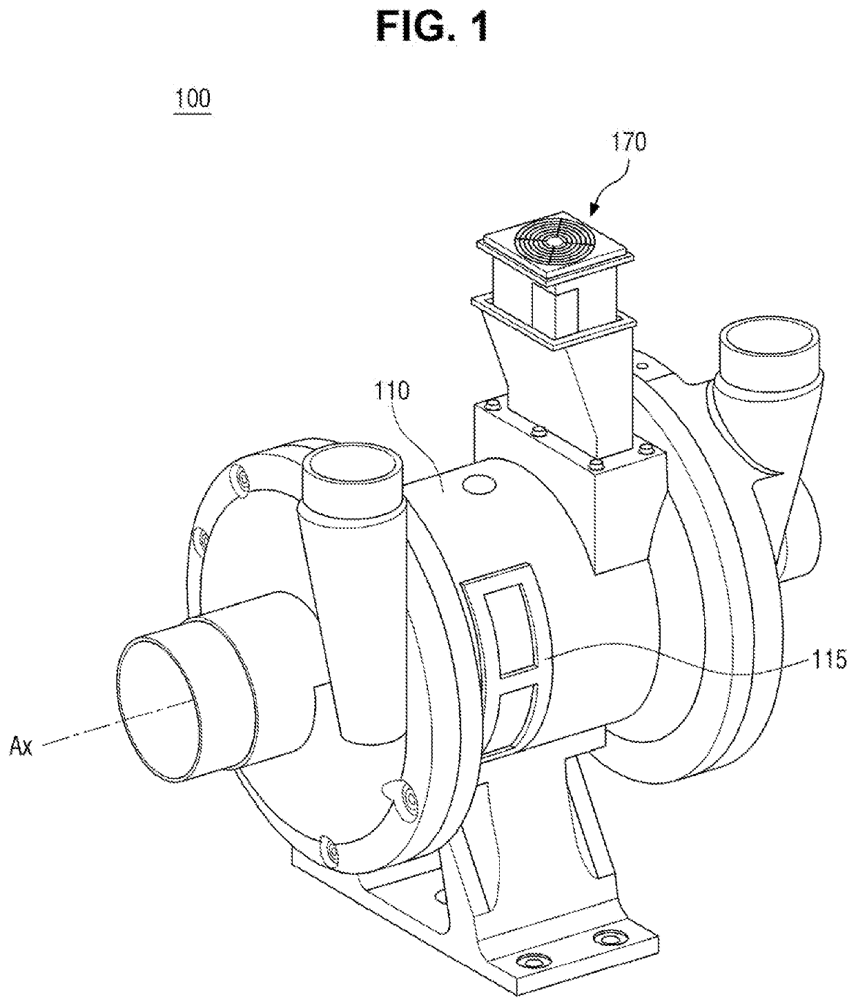
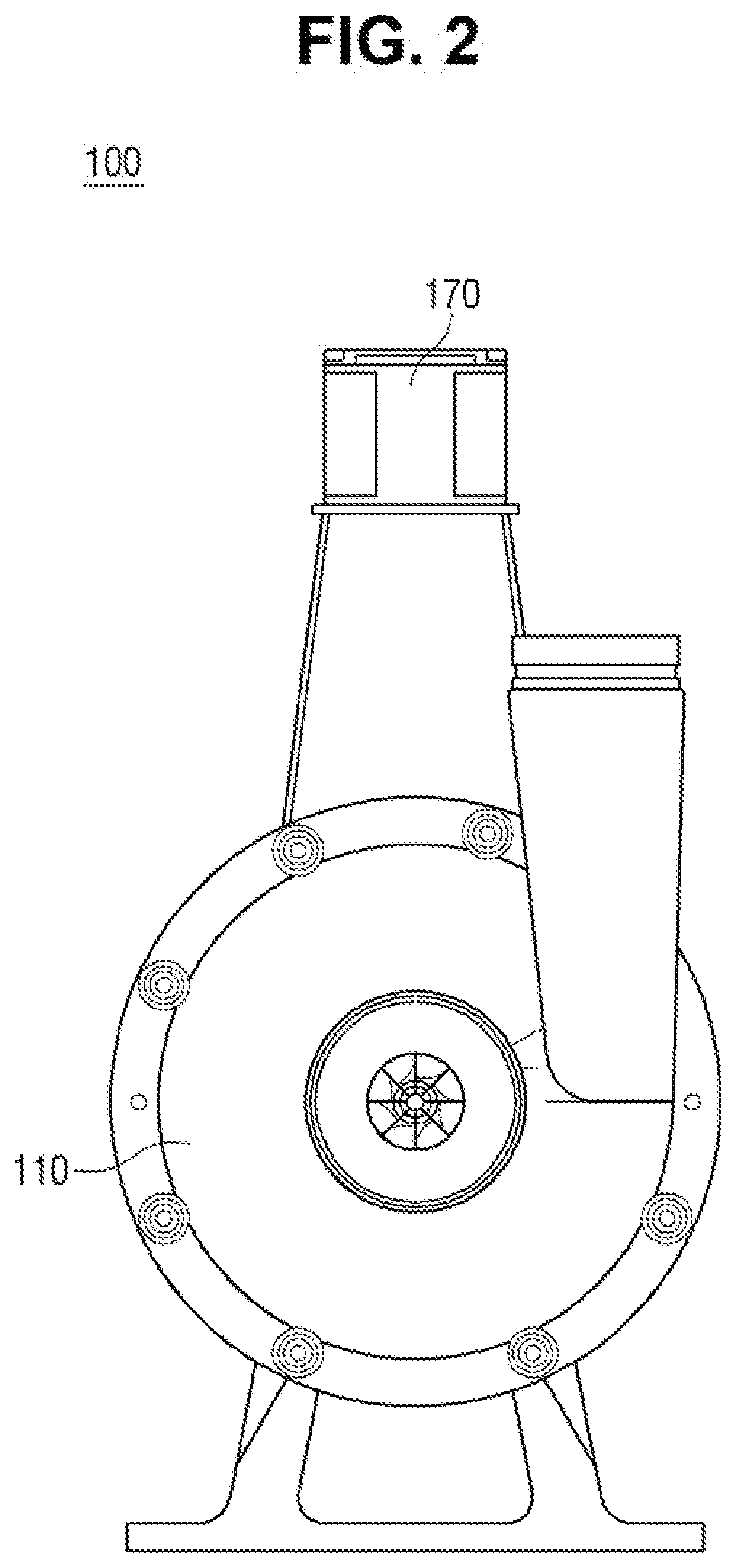
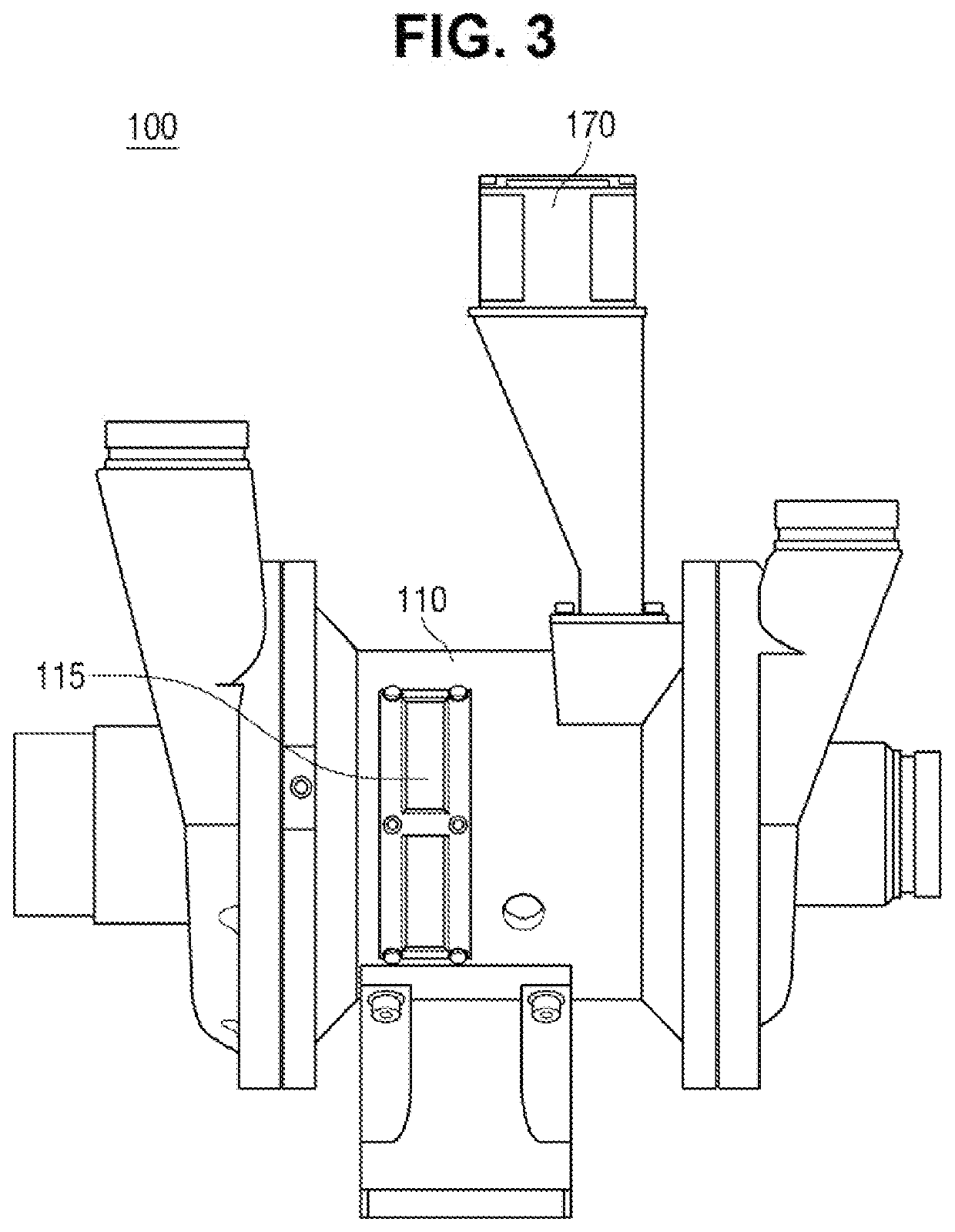

Image

  • Rotary device
  • Rotary device
  • Rotary device

Examples


Embodiment Construction

[0045]Embodiments of the present disclosure may have various modifications and include various embodiments. Therefore, some embodiments will be described in detail with reference to the drawings. However, this is not intended to limit the present disclosure to the specific embodiments described in detail. It is to be understood that all changes, equivalents, and substitutes included in the spirit and scope of the present disclosure are included.

[0046]The terminology used herein is for the purpose of describing particular example embodiments only and is not intended to be limiting of the present disclosure. Singular expressions include plural expressions unless the context clearly dictates otherwise. Herein, the terms such as “comprise” or “have” are intended to specify the presence of stated features, integers, steps, operations, components, parts, or combinations thereof. It should be understood that they do not preclude the possibility of presence or addition of one or more other ...


PUM


Abstract

A rotary device includes a housing; an impeller provided in the housing; a rotor disposed at a rear of the impeller, and configured to rotate; a stator disposed to surround the rotor; a bearing at the rear of the impeller, and configured to relieve friction caused by rotation of the rotor while supporting the rotor when the rotor is rotated; and a fan mounted to an outside of the housing, and configured to introduce external air into an inside of the housing and, after the external air is heated while travelling on a cooling flow path, release the external air to the outside of the housing.

Description

CROSS-REFERENCE TO THE RELATED APPLICATION[0001]This application is based on and claims priority under 35 U.S.C. § 119 to Korean Patent Application No. 10-2019-0066787 filed on Jun. 5, 2019, in the Korean Intellectual Property Office, the disclosure of which is incorporated by reference herein in its entirety.BACKGROUND1. Technical Field[0002]Embodiments of the present disclosure relate to a rotary device, for example, to a rotary device capable of cooling heat generated in internal structures when driving a rotor having a permanent magnet.2. Description of Related Art[0003]In accordance with the demand for the development of high-performance, high-power electrical equipment, rotary devices such as generators and electric motors are provided. Such rotary devices may comprise industrial compressors, pumps, or vehicle air supplies having a rotor-bearing structure. In order to provide driving to such rotary devices, a rotating body having a permanent magnet may be provided to be rotate...

Claims


Application Information

Patent Timeline
Patent Type & Authority Applications(United States)
IPC IPC(8): H02K9/06H02K5/167H02K5/18H02K5/20H02K7/08H02K9/18
CPCH02K5/20H02K9/06H02K5/18H02K7/085H02K5/1675H02K9/18H02K7/14H02K2205/03H02K1/20H02K5/207H02K2205/09F16C37/007
Inventor HWANG, JIN SEOKPARK, HONG GI
Owner HANWHA POWER SYST CO LTD
Learn More