
Sliding member

Active Publication Date: 2020-12-17
TAIHO INDUSTRIES CO LTD
View PDF0 Cites 0 Cited by
  • Summary
  • Abstract
  • Description
  • Claims
  • Application Information

AI Technical Summary

Benefits of technology

The present invention is aimed at providing a sliding member with an overlay that can prevent interlayer peeling while ensuring good fatigue resistance. The overlay contains a combination of soft and hard materials, where the hard material improves fatigue resistance. The concentration of the hard material increases with depth from the surface, which enhances conformability during initial wear and high wear resistance during advanced wear. This combination of hard and soft materials prevents interlayer peeling while ensuring good fatigue resistance.

Problems solved by technology

However, even if the interlayer adhesion is improved by adjusting the crystal grain size as in JP2006-266445 A, when the overlay has a two-layer structure, there is the problem that interlayer peeling cannot be avoided.
There is also the problem that abrupt changes in the bearing properties cannot be avoided during wear when the overlay has a two-layer structure.

Method used


Image

  • Sliding member
  • Sliding member
  • Sliding member

Examples


first embodiment

(1) FIRST EMBODIMENT

[0017](1-1) Configuration of the Sliding Member:

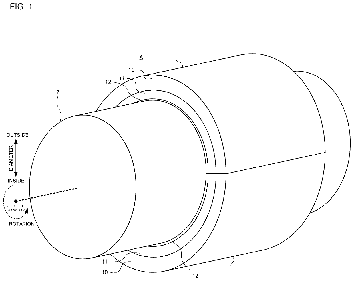
[0018]FIG. 1 is a perspective view of a sliding member 1 according an embodiment of the present invention. The sliding member 1 includes a back metal 10, a lining 11, and an overlay 12. The sliding member 1 is a half-split metal member formed by dividing a hollow tube into two parts in the radial direction and having a semi-circular arc cross section. A sliding bearing A is formed by assembling two sliding members 1 into a tubular shape. The sliding bearing A bears, in an internally formed hollow portion, a columnar counterpart shaft 2 (engine crankshaft). The outer diameter of the counterpart shaft 2 is formed slightly smaller than the inner diameter of the sliding bearing A. Lubricating oil (engine oil) is supplied in a gap formed between the outer circumferential surface of the counterpart shaft 2 and the inner circumferential surface of the sliding bearing A. With the lubricating oil thus supplied, the outer cir...


PUM

PropertyMeasurementUnit
Fractionaaaaaaaaaa
Fractionaaaaaaaaaa
Concentrationaaaaaaaaaa

Abstract

A sliding member includes an overlay formed with an alloy plated film of Bi and Sb, the Sb concentration increasing in the overlay with the depth from the surface of the overlay.

Description

BACKGROUND OF THE INVENTION1. Field of the Invention[0001]The present invention relates to a sliding member including an overlay of an alloy plated film of Bi and Sb.2. Description of the Related Art[0002]A sliding member including an overlay containing a Bi coating layer and an Ag intermediate layer is known (see JP2006-266445 A). In JP2006-266445 A, the size of the Ag crystal grains in the intermediate layer is adjusted to improve the interlayer adhesion of the overlay. The size of the Bi crystal grains in the coating layer is also adjusted to improve the adhesion and the fatigue resistance of the overlay.[0003]However, even if the interlayer adhesion is improved by adjusting the crystal grain size as in JP2006-266445 A, when the overlay has a two-layer structure, there is the problem that interlayer peeling cannot be avoided. There is also the problem that abrupt changes in the bearing properties cannot be avoided during wear when the overlay has a two-layer structure.SUMMARY OF ...

Claims


Application Information

Patent Timeline
IPC IPC(8): F16C33/12C10M103/04B22F7/08B22F5/10B22F3/24C25D3/56C25D7/10F16C17/02
CPCC25D7/10C10M2201/053B22F7/08F16C2204/36F16C33/124C10M103/04C25D3/56B22F3/24F16C33/1025C10N2050/08B22F5/106C22C1/0425F16C33/14C22C9/02B22F2003/242B22F2301/10F16C17/02C22C12/00C22C9/00F16C2204/34B22F5/003B22F2998/10B22F3/10B22F3/162B22F2003/247
Inventor ICHIKAWA, MASAYA
Owner TAIHO INDUSTRIES CO LTD
Features
  • Generate Ideas
  • Intellectual Property
  • Life Sciences
  • Materials
  • Tech Scout
  • Unparalleled Data Quality
  • Higher Quality Content
  • 60% Fewer Hallucinations
Learn More