Non-pneumatic tire

a non-pneumatic, tire technology, applied in the field of tires, can solve the problems of poor elasticity of tires, poor cushioning effect during driving, and inconvenient assembly of tires and rims

Pending Publication Date: 2020-12-24
HEBEI WANDA TIRE CO LTD
View PDF4 Cites 0 Cited by
  • Summary
  • Abstract
  • Description
  • Claims
  • Application Information

AI Technical Summary

Problems solved by technology

Because solid tires are supported by inner rubber compounds, the weight of the whole tire is heavier, the elasticity of the tire is poor, the cushioning effect during driving is poor, and the assembly of the tire and the rim is not convenient.
Although the weight is reduced, the air convection in the gaps of hollow honeycomb structure will significantly increase the noise during the driving.
During emergency braking, the rim is easily damaged due to deformation of the tire.
In addition, since the hollow support parts of the rim are easily damaged by collisions, the tires need to be replaced.
The tire has a small ground contact area, which does not provide enough traction and good comfort.

Method used


Image

  • Non-pneumatic tire
  • Non-pneumatic tire
  • Non-pneumatic tire

Examples


embodiment i

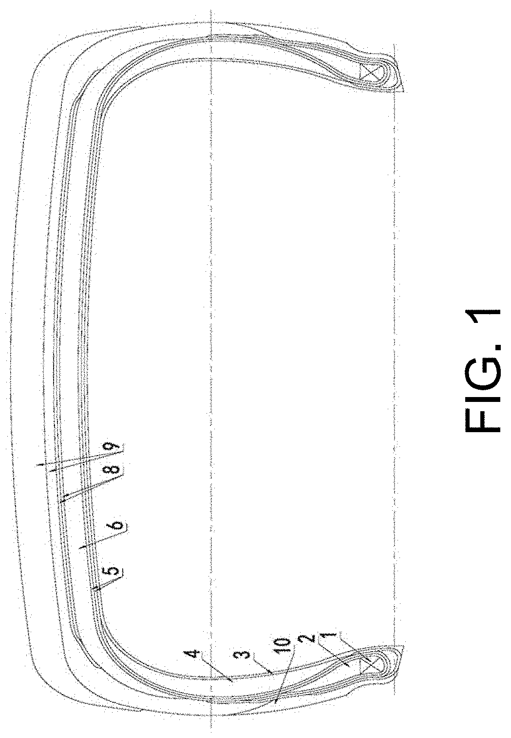
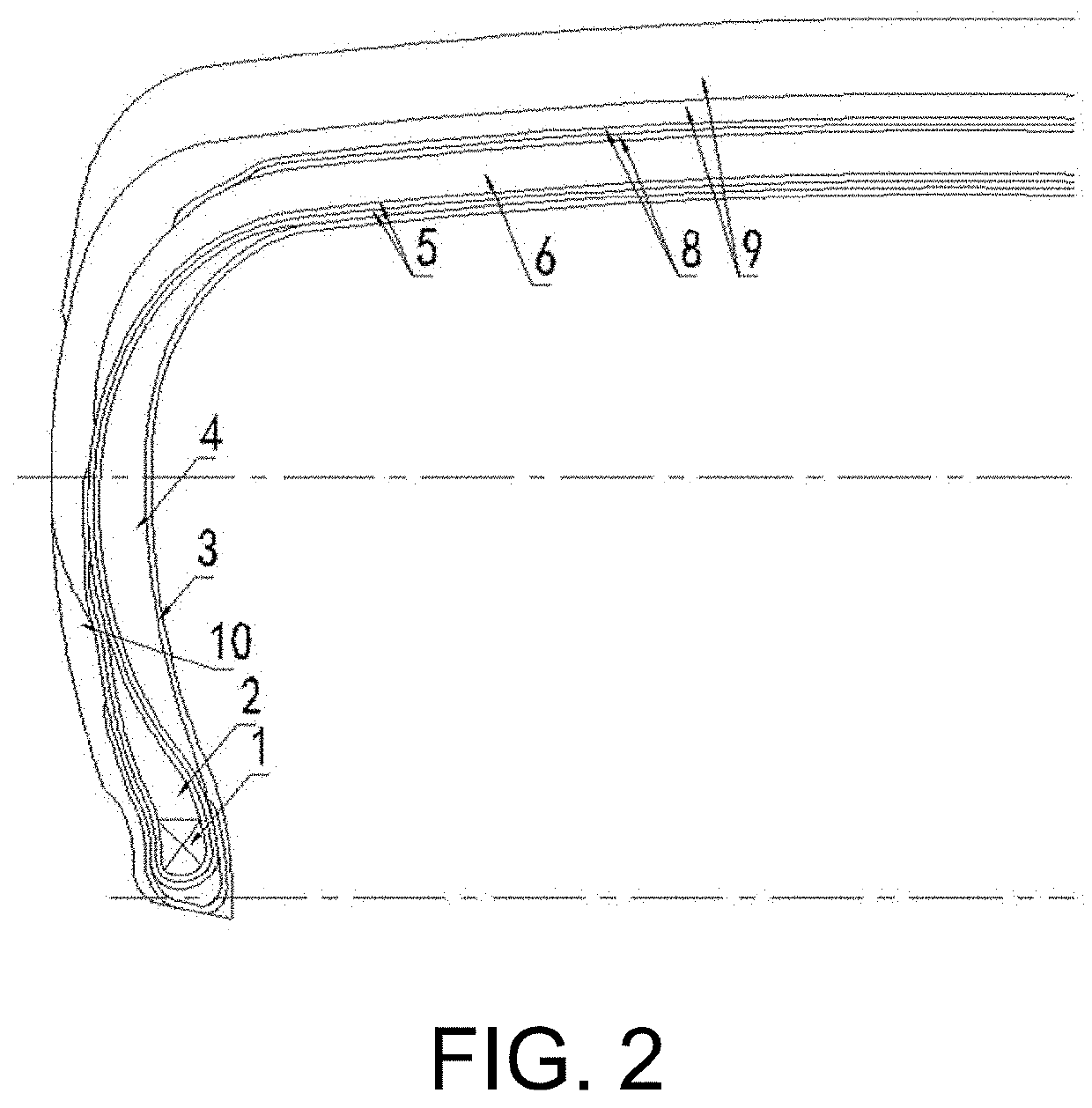
[0035]FIG. 1 and FIG. 2 illustrate embodiment I of the non-pneumatic tire of this application. As shown, the non-pneumatic tire includes beads 1, apexes 2, an inner liner 3, a cushion ply 8, a tread rubber 9, sidewall rubbers 10 and a first carcass ply 5. In addition, it includes sidewall support layers 4 and a crown support layer 6.

[0036]As shown, the inner liner 3 is located on the innermost side of the non-pneumatic tire. The sidewall support layers 4 are located at the locations of sidewalls of the non-pneumatic tire and interposed between the inner liner 3 and the first carcass ply 5. The apexes 2 are respectively located above the beads 1. Each apex 2 has a generally triangular cross section. Each apex 2 is partly overlapped with one sidewall support layer 4 with the first carcass ply 5 arranged between them. Both ends of the first carcass ply 5 respectively extend from the insides of the beads 1 to beneath the beads 1, and then to the outsides of the beads 1, so as to wrap th...

embodiment ii

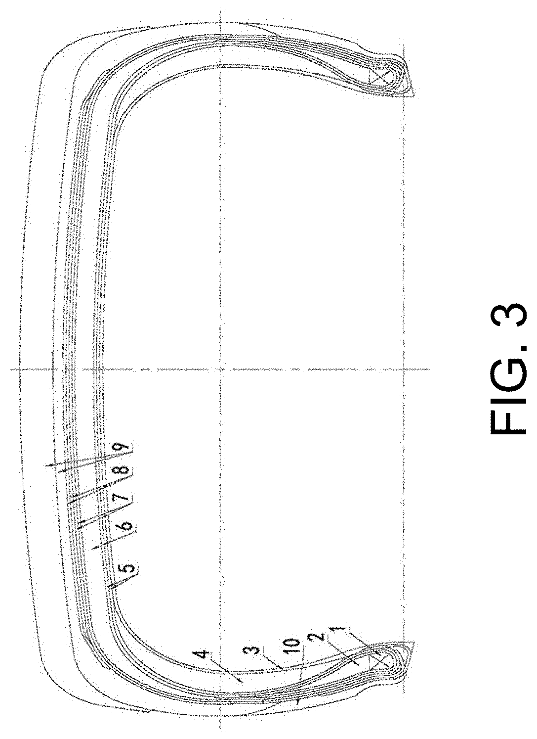
[0042]FIG. 3 and FIG. 4 illustrate embodiment II of the non-pneumatic tire of this application. Embodiment II is different from embodiment I in the following aspect. The non-pneumatic tire of embodiment II further includes a second carcass ply 7.

[0043]As shown, the sidewall support layers 4 are located at the locations of sidewalls of the non-pneumatic tire and interposed between the inner liner 3 and the first carcass ply 5. The first carcass ply 5 comprises two layers of carcass cords. The two layers of carcass cords are mutually crosswise arranged.

[0044]The second carcass ply 7 is arranged on the outside of the first carcass ply 5. The second carcass ply 7 has two layers of carcass cords. The two layers of carcass cords are mutually crosswise arranged. The inner layer of carcass cord of the second carcass ply 7 and the outer layer of carcass cord of the first carcass ply 5 are mutually crosswise arranged. Two ends of each layer of the carcass cord of the second carcass ply 7 resp...

embodiment iii

[0047]As shown in FIG. 5, embodiment III is different from embodiment II in the following aspects. The crown support layer 6 is arranged between the inner liner 3 and the first carcass ply 5. The two ends of the crown support layer 6 respectively extend to the two sidewalls, and are respectively overlapped with the upper half parts of the sidewall support layers 4. The first carcass ply 5, the second carcass ply 7 and the cushion ply 8 are arranged sequentially from inside to outside.


PUM

PropertyMeasurementUnit
thicknessaaaaaaaaaa
structureaaaaaaaaaa
weightaaaaaaaaaa

Abstract

A non-pneumatic tire includes beads, apexes, an inner liner, a cushion ply, a tread rubber, sidewall rubbers, and a first carcass ply; and further includes sidewall support layers and a crown support layer. The sidewall support layers are located at the locations of sidewalls and interposed between the inner liner and the first carcass ply. The crown support layer is located at the location of a crown, and interposed between the inner liner and the first carcass ply or between the first carcass ply and the cushion ply. Both ends of the crown support layer respectively extend toward the sidewalls and are partly overlapped with the sidewall support layers.

Description

CROSS-REFERENCE TO RELATED APPLICATION[0001]This application claims the priority benefit of China application No. 201910543104.X, filed on Jun. 21, 2019. The entirety of the above-mentioned patent application is hereby incorporated by reference herein and made a part of this specification.BACKGROUNDTechnical Field[0002]The present application relates to the technical field of tire, in particular to a non-pneumatic tire.Description of Related Art[0003]Conventional non-pneumatic tires mainly includes solid tire and honeycomb tire. These two kinds of tires do not need to be inflated, and can achieve a supporting function and a cushioning function only using its own material and structure. However, the two kinds of tires have the following disadvantages.[0004]Because solid tires are supported by inner rubber compounds, the weight of the whole tire is heavier, the elasticity of the tire is poor, the cushioning effect during driving is poor, and the assembly of the tire and the rim is not...

Claims


Application Information

Patent Timeline
Patent Type & Authority Applications(United States)
IPC IPC(8): B60C17/00B60C13/00B60C15/00
CPCB60C15/0009B60C17/0036B60C2017/0081B60C13/002B60C7/00B60C13/00B60C11/00B60C7/102B60C7/22B60C17/0009B60C7/125B60C15/0018B60C2013/006
Inventor GENG, PENGZHANG, QINGHUALIU, CHUAN
Owner HEBEI WANDA TIRE CO LTD
Why Eureka
Try Eureka