Waveguide and sensor based on same

a waveguide and sensor technology, applied in the field of waveguides and sensors, can solve the problems of not being able to tell which type of deformation is applied, no way to tell the location of deformation along the waveguide, and no distributive sensing can be achieved with such stretchable waveguides. the effect of low cos

Active Publication Date: 2021-01-07
CORNELL UNIVERSITY
View PDF1 Cites 4 Cited by
  • Summary
  • Abstract
  • Description
  • Claims
  • Application Information

AI Technical Summary

Benefits of technology

[0010]The present disclosure describes, in various examples, multicore, color-doped (color-dyed), stretchable waveguides, which can be designed as a compact and low cost optical waveguide sensor. The sensor can differentiate pressing, stretching, and bending deformations, and measure the location and magnitude of the deformation. In some embodiments, the sensor is made from elastomeric materials (e.g., soft elastomeric materials). As such, the sensor may be advantageous for use with various robotic actuators (e.g., soft robotic actuators). Through an innovative design and integrated electronics, a sensor can provide simultaneous distributive sensing and decouple multiple modes of deformation, with spatial sensitivity, e.g., down to sub-mm and a wide range.
[0011]Embodiments of the waveguides and sensors of the present disclosure offer various capabilities, including, for example, a tactile sensor that can detect and differentiate local pressure, curvature, and elongation, with simple setup, readily wireless connections, or a combination thereof. The data measured / obtained using the sensors offer desirable information in applications such as, for example, real time sensation in remote surgery, virtual reality (VR) glove, soft prosthetics and orthotics, and smart robotic hand and arms, and the like.

Problems solved by technology

Therefore, stretchable waveguide sensors provide conformable contact with the soft body being sensed at all times, which is not achievable by rigid sensors.
With these waveguides, from the output intensity, one can only tell if the waveguide is deformed, but cannot tell which type of deformation is being applied.
Furthermore, there is also no way to tell the location of the deformation along the waveguide with previous designs.
No distributive sensing can be achieved with such stretchable waveguides.
However, this method has, for example, the following downsides: (1) Optical fibers used in these applications are flexible but not stretchable, so they cannot conform well to soft and stretchy bodies.
(2) The instrument to measure wavelength shift is quite large, and does not allow for compact and wireless sensing for small soft robot and wearable gadgets.
Although this method is good at tactile sensing, it cannot sense any other deformations, such as bending and stretching, other than pressing.
Furthermore, this setup involves rigid pieces and defeats the goal of having entire sensor compliance to match the soft bodies.
Although this system offers better mechanical flexibility by decomposing rigid parts into small modules, it still does not offer true stretchability and conformability.
Furthermore, the spatial resolution of the sensor system depends on the density of the LED and photodiode modules, which is very power consuming.

Method used


Image

  • Waveguide and sensor based on same
  • Waveguide and sensor based on same
  • Waveguide and sensor based on same

Examples


example 1

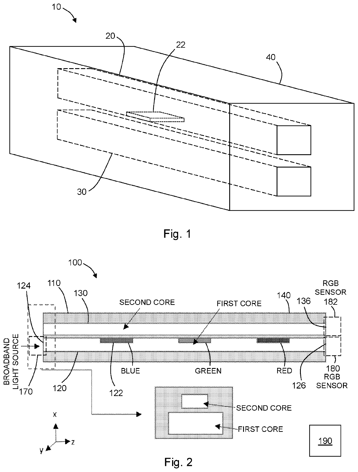
de, comprising a first core having a first refractive index; a second core having a second refractive index, the second core being spaced apart from and parallel with the first core; a cladding surrounding the first core and the second core, the cladding having a refractive index lower than the first refractive index and the second refractive index, and wherein an interstitial portion of the cladding is located between the first core and the second core; and wherein a first region of the first core adjacent to the cladding or of the cladding adjacent to the first core is color dyed.

example 2

uide of Example 1, wherein the first color-dyed region is of the first core and adjacent to the interstitial cladding.

example 3

uide of any one of the preceding Examples, wherein the first color-dyed region extends over a cross-sectional area of the first core which is less than or equal to 50% of a cross-sectional area of the first core.


PUM


Abstract

A waveguide is provided. The waveguide having a first core, a second core spaced apart from and parallel with the first core, and a cladding surrounding the first core and the second core. An interstitial portion of the cladding is located between the first core and the second core. A first region of the first core adjacent to the cladding or of the cladding adjacent to the first core is color dyed.

Description

CROSS-REFERENCE TO RELATED APPLICATIONS[0001]This application claims priority to U.S. Provisional Application No. 62 / 592,073, filed on Nov. 29, 2017, now pending, and U.S. Provisional Application No. 62 / 642,407, filed on Mar. 13, 2018, now pending, the disclosures of which are incorporated herein by reference.STATEMENT REGARDING FEDERALLY SPONSORED RESEARCH[0002]This invention was made with government support under contract no. N00014-17-1-2837 awarded by the Department of Defense. The government has certain rights in the invention.FIELD OF THE DISCLOSURE[0003]The present disclosure relates to force sensors, and in particular, sensors for use in soft robotics.BACKGROUND OF THE DISCLOSURE[0004]Stretchable optical waveguides made of elastomeric materials have been proven as effective sensors for soft robotics applications and wearable technologies. The elastic modulus and strain of these waveguide materials are close to that of soft robots and human skin. Therefore, stretchable wavegu...

Claims


Application Information

Patent Timeline
Patent Type & Authority Applications(United States)
IPC IPC(8): G01B11/16G02B6/122
CPCG01B11/16G02B2006/12138G02B6/1221G02B2006/12097G02B6/125G01L1/24G02B2006/12069
Inventor SHEPHERD, ROBERTBAI, HEDANLI, SHUOTU, YAQI
Owner CORNELL UNIVERSITY
Why Eureka
Try Eureka